Cutter Bar Drive for a Multi-Section Header for Attachment to Harvesters

Active Publication Date: 2017-04-20
CARL GERINGHOFF
2 Cites 7 Cited by

AI-Extracted Technical Summary

Problems solved by technology

Separate bearings, holding devices, and co...

Benefits of technology

[0015]The shaft of the deflection roller itself can be used as a force transmitting means or the shaft of the deflection roller is designed as a hollow shaft through which a separate (second) drive shaft is extended. The separate (second) drive shaft can also be extending adjacent to a deflection roller and independent of it. This has the advantage that the working rotary speed of the deflection roller and of the separate drive shaft can be controlled separately. For example, in this solution it is possible to continue to run the belt conveyor, while the cutter drive is switched off or the cutter drive can be started while the belt conveyor is still standing in order to keep the starting torques low. The separate drive shaft forms a good support of the deflection roller against buckling when the belts of the belt conveyor are tensioned. Different speeds of the deflection roller and of the separate drive shaft can be adjus...

Abstract

A header for stalk crop has a multi-part cutter bar with oscillatingly driven cutter bar parts. Cutter bar knives of the cutter bar interact with counter knives connected to header frame. A drive shaft ends in a first plane inside a gear housing arranged behind the cutter bar. An eccentric shaft supported in the gear housing carries a gear wheel arranged in a second plane above or below the first plane. The drive shaft drives the gear wheel through a bevel gear. First and second eccentric discs, arranged in third and fourth planes, respectively, are connected to the eccentric shaft; first and second eccentric levers are correlated therewith. First and second pivot levers are connected to the first and second eccentric levers and connected to stationarily supported pivot shafts. Crank arms connected to the pivot shafts, respectively, transmit their pivot movement to the cutter bar parts.

Application Domain

Technology Topic

Image

  • Cutter Bar Drive for a Multi-Section Header for Attachment to Harvesters
  • Cutter Bar Drive for a Multi-Section Header for Attachment to Harvesters
  • Cutter Bar Drive for a Multi-Section Header for Attachment to Harvesters

Examples

  • Experimental program(1)

Example

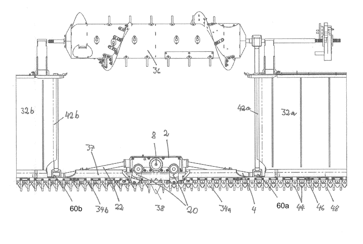
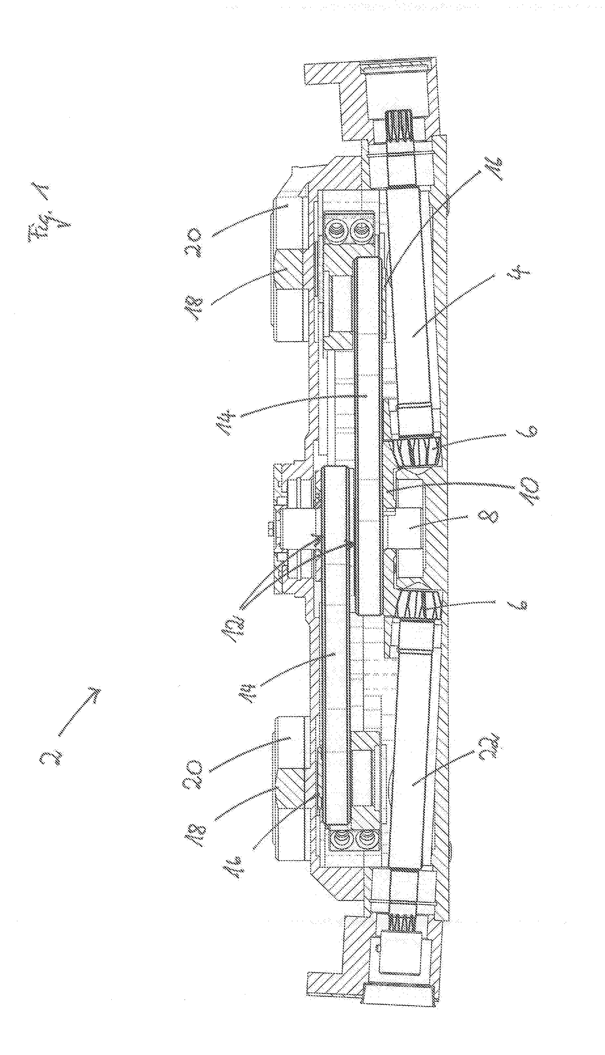
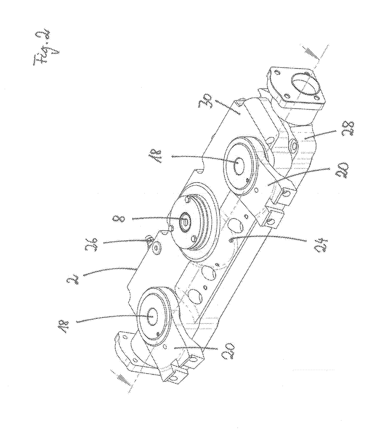
[0028]In FIG. 1 a gear housing 2 is shown in a section view. In the lowermost plane of the gear housing 2, the drive shaft 4 extends into the gear housing 2. By means of a bevel gear 6 the rotary speed of the drive shaft 4 is transmitted to the gear wheel 10 that is fixedly arranged on the eccentric shaft 8 in a second plane above the drive shaft 4. In the embodiment, the drive shaft 4 is arranged approximately parallel to the cutter bar 34. In transverse direction, the drive shaft 4 is angled relative to the cutter bar 34 by some angular degrees in the horizontal and vertical planes. The same holds true for the output shaft 22. By means of the gear wheel 10, the eccentric shaft 8 is rotated also.
[0029]On the eccentric shaft 8 which is substantially installed in vertical direction into the gear housing 2, two eccentric discs 12, which are hidden by the eccentric levers 14 in the section view of FIG. 1, are arranged in the third and fourth planes. The eccentric levers 14 are joined for articulation to pivot levers 16 which in turn are connected fixedly to a pivot shaft 18. The pivot shafts 18 project from the gear housing 2 upwardly and transmit their rotary movement to crank arms 20 which are fixedly attached to the pivot shafts 18. The pivot movements of the crank arms 20 are transmitted by connecting elements, not illustrated in detail in the drawing, to a respective cutter bar part.
[0030]The rotary movement of the drive shaft 4 is transmitted by gear wheel 10 to the output shaft 22 which is arranged on the opposite side of the gear housing 2 relative to the eccentric shaft 8. The transmission of the rotary movement of the drive shaft 4 to the output shaft 22 represents a through drive of the drive force.
[0031]In FIG. 2, the gear housing 2 is shown in a closed state in a perspective view from above. This view indicates the drive shaft 4 and the output shaft 22. Also, the two crank arms 20 which are oriented forwardly toward the cutter bar can be seen well; in harvesting operation they carry out an oscillating movement that is transmitted to the cutter bar parts. Also, the cover of the eccentric shaft 8 can be seen well. The pivot shafts 18 to which the crank arms 20 are fastened are located forwardly in the gear housing 2 in comparison to the eccentric shaft 8. When in this specification reference is being had to front and rear, front always means the direction in which, for harvesting, the header is moved into the crop to be harvested and rear the direction in which the harvester is positioned to which the header is attached.
[0032]In FIG. 2 also the slanted surface 24 can be seen well which is designed to descend to the front. Moreover, FIG. 2 also shows the horizontally extending division between the gear housing bottom 28 and the gear housing cover 30. At the rear of the gear housing 2 there is also an oil connector 26 through which by means of a hydraulic pump, not illustrated in detail in the drawing and located in the interior of the gear housing 2, oil can be dispensed into a cooling circuit and/or pressure oil can be dispensed for actuation of a hydraulic valve, also not illustrated in the drawing.
[0033]FIG. 3 shows a perspective view from the front of the conveying members of a header wherein parts of the header are not shown in this view. The header bottom is formed in this embodiment by the top side of the conveying members in the form of belt conveyors 32a, 32b wherein the central belt conveyor which conveys the crop to the rear is not shown. The two illustrated belt conveyors 32a, 32b each convey the crop placed on them transversely to the travel direction onto the central belt conveyor. In the perspective view from the front illustrated in FIG. 3, it can be seen that in the embodiment the drive shaft 4 and the output shaft 22 in the vertical plane are not extending precisely parallel to the cutter bar 34 but drop downwardly by a few angular degrees toward the sides. However, they have in approximation the same orientation as the cutter bar 34.
[0034]Between the cutter bar 34 and the top side of the belt conveyors 32a, 32b, there is a step 37 across which the cut crop must glide after the cut. In the view of FIG. 3, it can be seen that the height of the gear housing 2, despite the four different planes in its interior, is still more flat than the step 37 that must be surmounted in the area of the lateral belt conveyors 32a, 32b The gear housing 2 however is also so short that, behind it, a belt conveyor conveying to the rear can be easily arranged which conveys the crop into the effective range of a rotatingly driven intake roller 36 as an additional conveying member for the crop.
[0035]The cutter bar 34 is divided in the embodiment into two cutter bar parts 34a, 34b whose separation line is approximately in the area of the haulm divider 38. Both cutter bar parts 34a, 34b are driven by the drive device in the gear housing 2 by means of the drive shaft 4. The (first) drive shaft 4 is connected by a bevel gear 60a to the separate (second) drive shaft 40 with which the drive force is transmitted from the rear of the header to the front. The separate drive shaft 40 is positioned approximately parallel to the deflection roller 42a of the neighboring belt conveyor 32.
[0036]The output shaft 22 ends in the embodiment illustrated in FIG. 3 at a bevel gear 60b by means of which the deflection roller 42b of the left conveyor 32b is driven. In this way, the left belt conveyor 32b is driven from the rear of the header by the drive device for the cutter drive.
[0037]FIG. 4 shows a view from above of a drive train in which a separate (second) drive shaft 40 is formed by a deflection roller 42a which is designed as a hollow shaft of the transversely conveying belt conveyor 32a. As in the embodiment illustrated in FIG. 3, here also the deflection roller 42b is driven from the rear of the header by the drive device for the cutter drive. The view from above shows that the drive shaft 4 and the output shaft 22 in the horizontal plane are not precisely parallel to the cutter bar 34 but, relative to the side, are oriented toward the front by a few angular degrees. Essentially, the drive shaft 4 and the output shaft 22 are however extending in the horizontal plane in approximation parallel to the cutter bar 34, approximately in the space of an imaginary lateral extension of the gear housing 2, so that a short and flat configuration of the drive device is possible. The bevel gears 60a, 60b adjoining in lateral direction the drive shaft 4 and the output shaft 22 are arranged in the area behind the cutter bar 34.
[0038]In the view from above in FIG. 4, the cutter bar knives 44 which are fastened to the cutter bar parts 34a, 34b can be seen; upon transverse movement of the cutter bar parts 34a, 34b, the cutter bar knives 44 carry out a scissor-like cutting movement in interaction with the counter knives 46 which can be embodied on the mowing guards 48 or as separate knives. In the view from above it can also be seen well that the drive device according to the invention for the cutter bar is extremely short and provides sufficient free space for a belt conveyor or a rigid header bottom adjoining downstream in the conveying direction the cutter bar and the step for transporting away the cut crop.
[0039]The invention is not limited to the afore described embodiments. A person of skill in the art will have no problems with modifying the embodiments in a way appearing suitable to him in order to adapt them to a concrete application situation.
[0040]The specification incorporates by reference the entire disclosure of German priority document 10 2015 116 890.1 having a filing date of Oct. 05, 2015.
[0041]While specific embodiments of the invention have been shown and described in detail to illustrate the inventive principles, it will be understood that the invention may be embodied otherwise without departing from such principles.

PUM

no PUM

Description & Claims & Application Information

We can also present the details of the Description, Claims and Application information to help users get a comprehensive understanding of the technical details of the patent, such as background art, summary of invention, brief description of drawings, description of embodiments, and other original content. On the other hand, users can also determine the specific scope of protection of the technology through the list of claims; as well as understand the changes in the life cycle of the technology with the presentation of the patent timeline. Login to view more.

Similar technology patents

Deep and large foundation pit angle supporting horizontal shearing resistance structure

ActiveCN103967018AEnhanced horizontal shearGood supportExcavationsShear force
Owner:SHENZHEN GONGKAN GEOTECHN GRP

Chopping block type scissor for loom for shearing fabric in chopping manner

InactiveCN101333724AIncrease contact surface and frictionGood supportLoomsSevering textilesCamEngineering
Owner:JINGWEI TEXTILE MASCH CO LTD

Classification and recommendation of technical efficacy words

Why Eureka
Try Eureka