Adjustable headrest bracket

a headrest bracket and adjustable technology, applied in the direction of chairs, seats, transportation and packaging, etc., can solve the problems of hand tools, inconvenient or economic effectiveness of the approach, and complicated structure, and achieve the effect of facilitating the adjustmen

Inactive Publication Date: 2007-03-08
ASIASONIC INT INDAL
View PDF8 Cites 16 Cited by
  • Summary
  • Abstract
  • Description
  • Claims
  • Application Information

AI Technical Summary

Benefits of technology

This patent describes an improved way to attach a headrest to a car seat. A special bracket is used that allows for easy adjustment of the distance between the seats without requiring tools or changing parts. This makes it easier to customize the comfort level of each person's seat.

Problems solved by technology

The technical problem addressed in this patent is how to create a more efficient and economically feasible way to adapt headrests to different types of car seats without having to constantly change out parts. Current methods require expensive modifications to be made to each seat type when trying to install a specific headrest, which causes difficulties during assembly and maintenance. There needs to be a solution to allow for easy customization while reducing costs associated with production and labor.

Method used


Image

  • Adjustable headrest bracket
  • Adjustable headrest bracket
  • Adjustable headrest bracket

Examples


Embodiment Construction

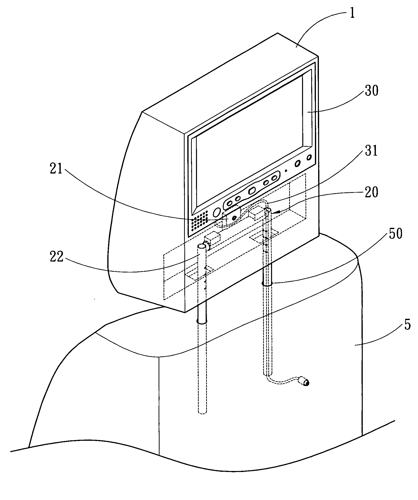
[0017] Please refer to FIGS. 3 and 4, the headrest 1 of the invention is installed on a vehicle seat 5. It has a base 10 and headrest brackets 22 formed by a structure 20. The base 10 has a housing space on one side to hold a display panel 30. The base 10 is fastened to a hollow coupling member 21 through a fastening element 40 that has coupling holes 212 on two ends. The fastening element 40 runs through a fastening hole 211 formed on the coupling member 21 to be fastened to the base 10 (the coupling member may also be integrally formed on the base 10). The coupling holes 212 aim to hold the two headrest brackets 22. Each of the headrest brackets 22 is bent to form a hinge end 221 and an insertion end 222. The insertion end 222 is inserted into a mating insertion hole 50 on the vehicle seat 5 that is formed to install the headrest 1. The hinge end 221 is inserted into the coupling hole 212 (or encases the coupling hole 212) to form a tight coupling. Thereby the headrest bracket 22 ...


PUM


Abstract

An adjustable headrest bracket includes a base and a coupling member located on the base. The coupling member has two coupling ends to couple with two separated headrest brackets. Each of the headrest brackets has an insertion end insertable into a vehicle seat and a hinge end coupled on the coupling end. Each of the headrest brackets forms a swivel path about the hinge end and a horizontal moving path relative to the coupling member. Thereby the interval of the headrest brackets can be adjusted to be inserted into different types of vehicle seats.

Description


Claims


Application Information

Patent Timeline
Owner ASIASONIC INT INDAL
Why Eureka
Try Eureka