
Axle spindle and wheel end assembly

a technology of axle spindle and end assembly, which is applied in the direction of shaft assembly, mechanical apparatus, transportation and packaging, etc., can solve the problems of reducing the performance of the axle, comparatively less robust construction, and less robust axle spindl

Inactive Publication Date: 2007-03-08
HENDRICKSON USA L L C
View PDF16 Cites 14 Cited by
  • Summary
  • Abstract
  • Description
  • Claims
  • Application Information

AI Technical Summary

Benefits of technology

[0014] An objective of the present invention is to provide an axle spindle and a wheel end assembly that are capable of selectively accommodating a dual-wheel, standard-tire configuration and a single-wheel, two-inch offset wide-tire configuration in a relatively economical manner.
[0015] Another objective of the present invention is to provide an axle spindle and a wheel end assembly that are capable of selectively accommodating a dual-wheel, standard-tire configuration and a single-wheel, two-inch offset wide-tire configuration in a relatively lightweight manner.
[0016] Yet another objective of the present invention is to provide an axle spindle and a wheel end assembly that are capable of selectively accommodating a dual-wheel, standard-tire configuration and a single-wheel, wide-tire configuration without modifications to the vehicle frame, subframe, axle and / or suspension assemblies.

Problems solved by technology

Therefore, the wheel end assembly must be sealed to prevent leakage of the lubricant, and also to prevent contaminants from entering the assembly, both of which could be detrimental to its performance.
As a result, the hub, bearing assembly and axle spindle for a dual-wheel, standard-tire configuration typically are of a comparatively less robust construction than the hub, bearing assembly and axle spindle used with types of wheel configurations that have a load line which is further outboard.
Due to common wheel attachment interfaces, such a less robust axle spindle and wheel end assembly construction may also selectively accommodate a single-wheel, wide-tire configuration, in which one wheel with a single wide tire mounted thereon is in turn mounted on the hub.
However, the less robust construction of the axle spindle and the wheel end assembly limits the range of single-wheel, wide-tire types to ones having only a zero offset or a near-zero offset, such as an 0.56-inch offset, to keep the load line in a location that is similar to that of the above-described dual-wheel, standard-tire configuration.
Any other type of single-wheel, wide-tire configuration moves the load line further outboard, and thus places an increased load on the outboard bearing of the bearing assembly, which causes that bearing to experience increased fatigue loading and significantly reduces its useful life.
However, a single-wheel, wide-tire with a zero offset has a narrower wheel base than a dual-wheel, wide tire configuration, which creates certain disadvantages when it is desired to change from one type of wheel configuration to another on a heavy-duty vehicle, such as a semi-trailer.
The time and expense for such modifications associated with roll stability thereby reduce the desirability of a zero-offset single-wheel, wide-tire configuration for a less robust axle spindle and wheel end assembly.
Since the load line of the two-inch offset wheel configuration is further outboard, a greater moment arm is created, leading to increased loading on the components of the axle spindle and the wheel end assembly.
However, the disadvantage of such more robust axle spindles and wheel end assemblies is that they are typically relatively heavy and / or expensive, and are not optimized for the different load line conditions of a dual-wheel, standard tire configuration and a single-wheel, wide tire configuration, which are undesirable characteristics.
However, the increased weight and / or cost associated with the more robust axle spindle and wheel end assembly are undesirable.

Method used


Image

  • Axle spindle and wheel end assembly
  • Axle spindle and wheel end assembly
  • Axle spindle and wheel end assembly

Examples


Embodiment Construction

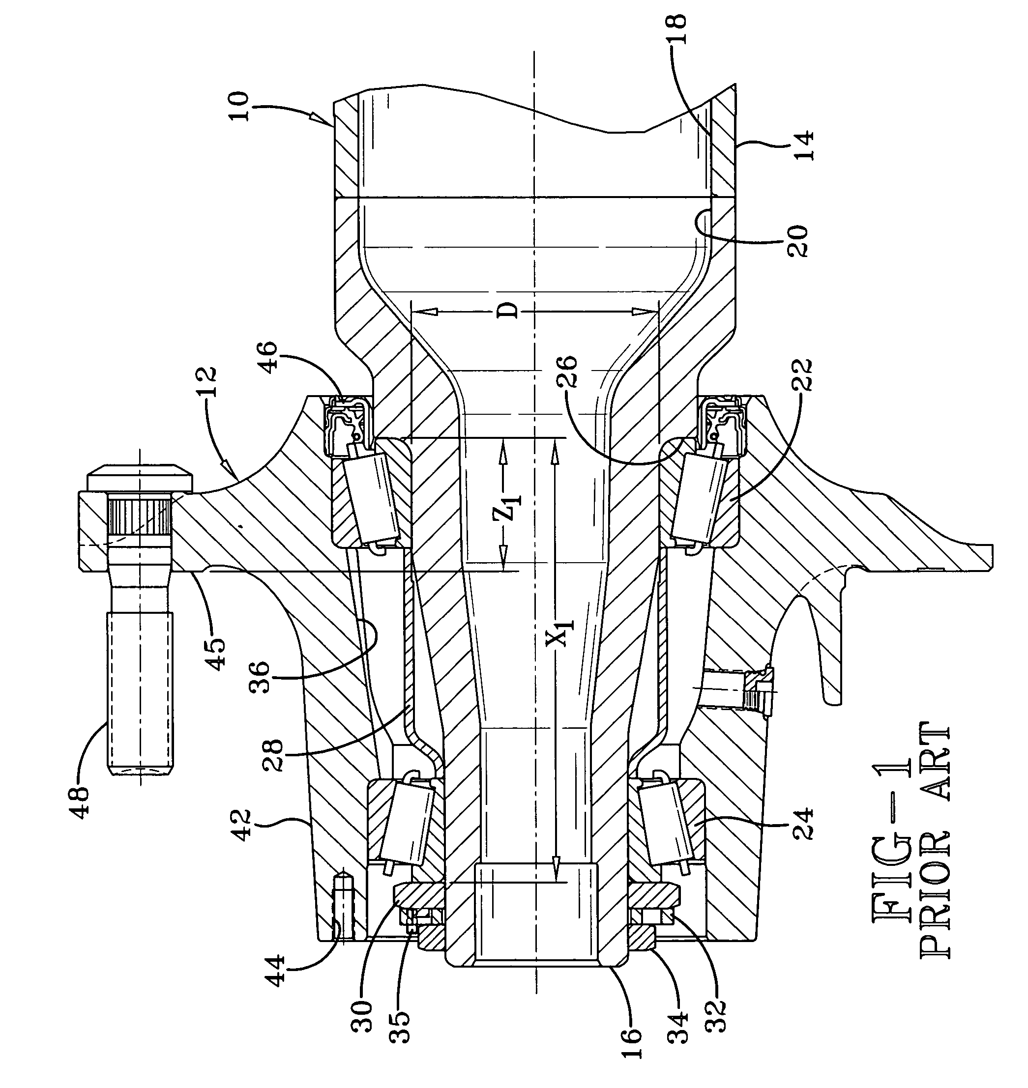
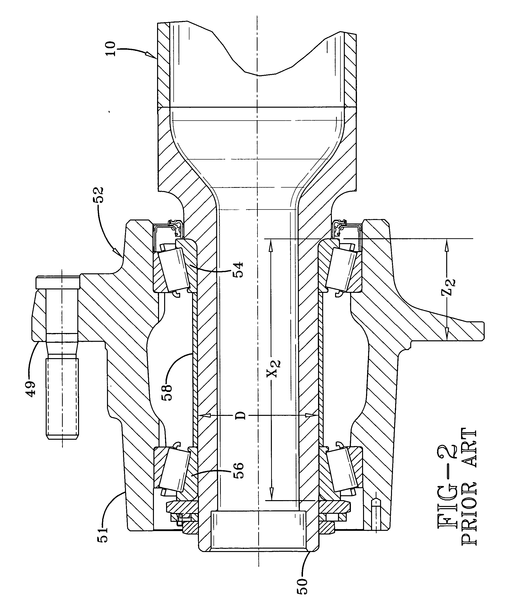
[0025] In order to better understand the axle spindle and wheel end assembly of the present invention, a less robust prior art axle spindle and wheel end assembly for a heavy-duty vehicle, typically used for an economical dual-wheel, standard-tire configuration, is shown in FIG. 1 and now will be described. Axle 10 depends from and extends transversely across the trailer of a heavy-duty tractor-trailer (not shown). A typical heavy-duty tractor-trailer includes one or more non-drive axles 10 suspended from the trailer, with each of the axles having a wheel end assembly 12 mounted on each end of the axle. For the sake of clarity, only one axle end and wheel end assembly 12 will be described herein. Axle 10 includes a central tube 14, and an axle spindle 16 is integrally connected by any suitable means, such as welding, to each end of the central tube. Axle central tube 14 generally is tubular-shaped and is formed with an internal cavity 18. Axle spindle 16 is tapered and is formed wit...


PUM


Abstract

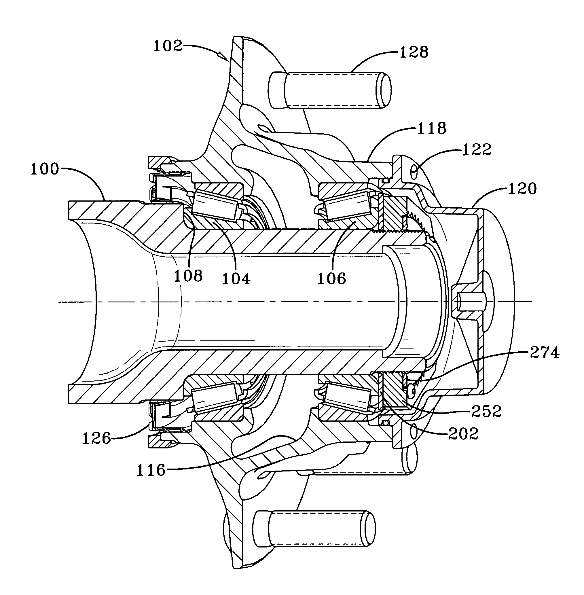
An axle for a heavy-duty vehicle extends transversely across the vehicle and includes a central portion. Each one of a pair of relatively short and lightweight axle spindles is connected to and extends outboardly from a respective end of the axle central portion. A wheel end assembly is rotatably mounted on each axle spindle. Each wheel end assembly includes spaced-apart inboard and outboard bearings that are immovably mounted on a respective axle spindle, and the bearings preferably are standard heavy-duty vehicle stock-type bearings that have respective inner diameters that are generally the same size. A relatively short and lightweight wheel hub is rotatably mounted on the bearings so that the wheel end assembly selectively accommodates a dual-wheel, standard-tire configuration and a single-wheel, wide-tire configuration, including a two-inch offset wheel.

Description

CROSS-REFERENCE TO RELATED APPLICATION [0001] This application claims the benefit of U.S. Provisional Patent Application Ser. No. 60 / 713,887, filed on Sep. 2, 2005.BACKGROUND OF THE INVENTION [0002] 1. Technical Field [0003] The invention relates to vehicle axles and wheel end assemblies, and in particular to axles and wheel end assemblies for heavy-duty vehicles, such as tractor-trailers. More particularly, the invention is directed to a heavy-duty axle spindle and wheel end assembly that are capable of selectively accommodating a conventional dual-wheel, standard-tire configuration and a single-wheel, wide-tire configuration in a robust, yet economical and lightweight manner. [0004] 2. Background Art [0005] For many years, the heavy-duty vehicle industry has utilized wheel end assemblies which typically are mounted on each end of one or more non-drive axles. Each wheel end assembly typically includes a hub rotatably mounted on a bearing assembly that in turn is immovably mounted o...

Claims


Application Information

Patent Timeline
IPC IPC(8): B60B27/00
CPCB60B27/001F16C19/364F16C19/548F16C2326/02F16C2240/40B60B27/02F16C25/06F16C2226/60Y02T10/86
Inventor WHITE, JAY D.
Owner HENDRICKSON USA L L C
Learn More