Hydraulic Oscillator For Use in a Transmitter Valve

a technology of hydrostatic oscillator and transmitter valve, which is applied in the field of measuring while drilling (mwd) systems, can solve the problems of reducing the accuracy of the transmitted puls

Inactive Publication Date: 2007-03-08
COLLETTE HERMAN D
View PDF21 Cites 4 Cited by
  • Summary
  • Abstract
  • Description
  • Claims
  • Application Information

AI Technical Summary

Benefits of technology

[0009] The present invention addresses these and other drawbacks in the art by employing a secondary mechanical ‘sense piston’ that forces a positive bystable valve state transition. A second latch means is used to preferentially lock the sense piston in one of two states providing either an high pressure poppet position or a low pressure poppet position. Alternatively, the latch means can be disengaged and the oscillator action will be observed.

Problems solved by technology

Unfortunately, these pressure increases were of relatively low frequency, generally resulting in a pressure pulse with a rise time of 20-200 milliseconds, a duration of 0.25 to 3 seconds, and a fall time of 20-200 milliseconds.
In addition to severely limiting the data transmission rate, these low frequencies coincide with the noise frequencies generated during drilling.
Unfortunately, conventional filtering, which is used to eliminate drilling noise, also removes much of the remaining energy from the transmitted pulse.
However, erosion of the poppet and orifice by the pressure pulses is a function of the imposed pressure drop.
Thus, increasing the pressure drop decreased pulser life.
Another problem with simply increasing the amplitude of the induced pressure pulses was the power required to create such pulses.
The large power demand meant a large and more powerful prime mover to operate the poppet, and this meant greater weight and cost for the MWD system.
While the structure and method shown and described in the '706 patent have been successful, the oscillator shown and described does not function well at low flow rates for the conduit conveyed fluid.
At low flow rate, the pressure differential across the oscillator is low, and if this differential falls below a certain differential pressure, the bistable valve prematurely lifts off the seat.
This lift increases the leakage of the bistable valve and may result in a leakage rate insufficient to engage the secondary spring means.

Method used


Image

  • Hydraulic Oscillator For Use in a Transmitter Valve
  • Hydraulic Oscillator For Use in a Transmitter Valve
  • Hydraulic Oscillator For Use in a Transmitter Valve

Examples


Embodiment Construction

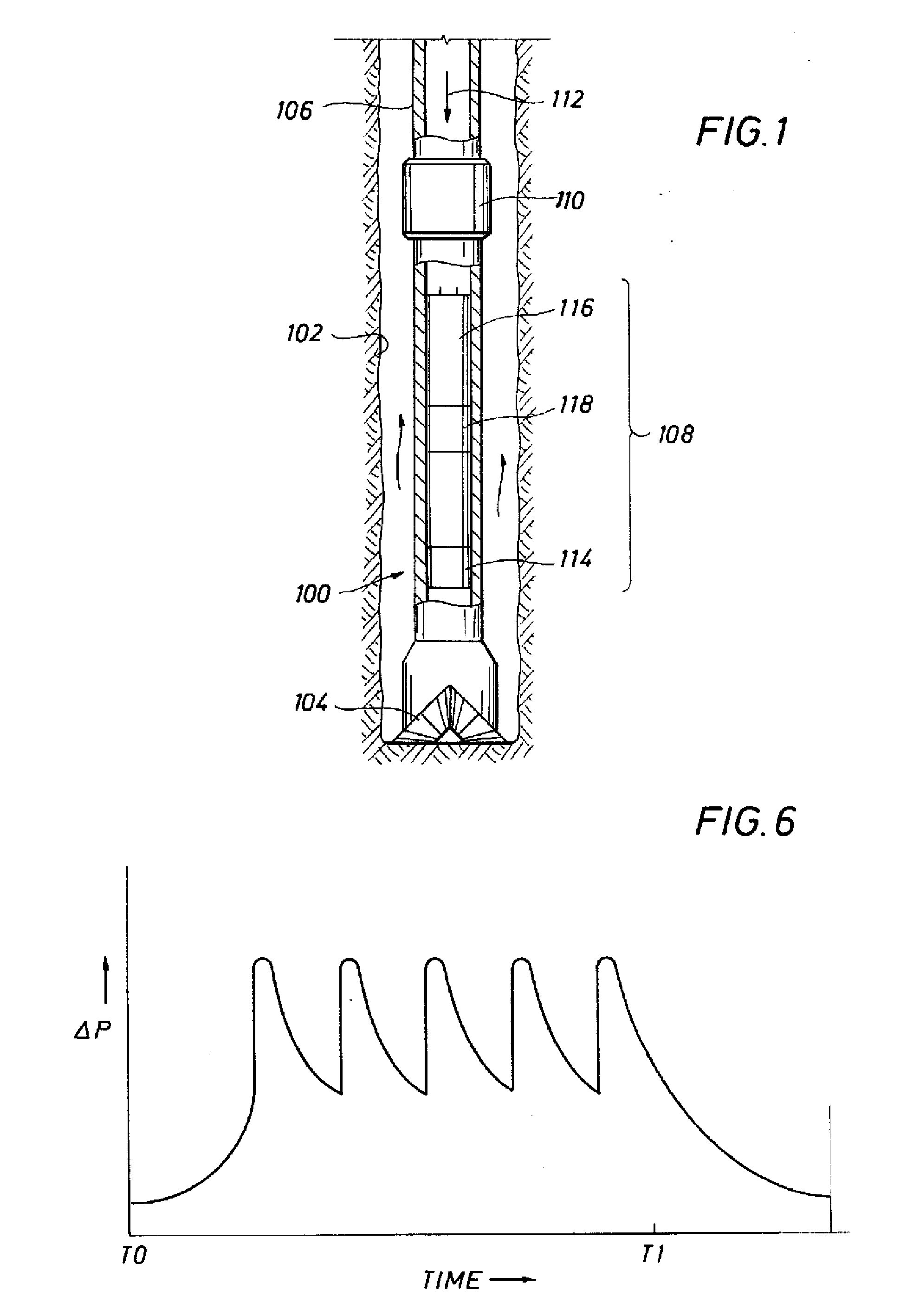
[0019]FIG. 1 illustrates a basic drilling system 100 in a bore hole 102 formed by a typical drill bit 104. The drill bit 104 is driven by a drill pipe 106 which joins to a bottom hole assembly 108 with a coupling 110. Drilling mud flows down through the drill pipe 106, as shown by an arrow 112, through the bottom hole assembly 108, through the drill bit 104 and back to the surface by way of the annulus between the drill pipe and the bore hole.

[0020] In drilling applications, the bottom hole assembly 108, between the coupling 110 and the drill bit 104, is where the present invention finds application. The bottom hole assembly 108 includes one or more sensors 114 adapted to measure parameters of interest. The sensor(s) 114 provide a sensor signal to a transmitter 116 which includes a pulser 118. The transmitter 116 and pulser 118 vary the pressure in the drilling fluid, which variation is detected at the surface and interpreted to provide the measured data at the surface. These senso...


PUM


Abstract

An oscillating valve driven by the pressure in a mud pulser develops a pressure variation in the mud pulse signal that is at a frequency that is different than the frequencies of the mud system. The oscillating valve is coupled to or integral with the pulse drive cylinder, whether the drive means for operation of the pulser is upstream or downstream from the orifice. A bistable valve improves performance of the transmitting element at low flow rates by providing a toggle mechanism which assures positive seating of the bistable valve.

Description

FIELD OF THE INVENTION [0001] The present invention relates generally to the field of measuring while drilling (MWD) systems, and, more particularly, to a system which provides repeated, cyclic pressure oscillations for the transmission of data from sensors to receivers located at some distance removed and connected to the transmitter by a conduit. BACKGROUND OF THE INVENTION [0002] Remotely operated sensor packages have been used during the drilling of wells for a number of years. Similar systems are used in sewer line cleaning systems. The sensor packages are commonly found in applications where information such as the inclination, azimuth, and various logging sensor measurements are of interest. [0003] During well drilling operations, drilling fluid, known in the art as drilling mud, is typically pumped down through the drill pipe and then through the drill bit to clean, lubricate, and cool the bit. The drilling fluid then returns to the surface by way of the annulus between the ...

Claims


Application Information

Patent Timeline
Patent Type & Authority Applications(United States)
IPC IPC(8): H04H9/00G01V3/00H04H60/31
CPCG01V11/002E21B47/187E21B47/24
Inventor COLLETTE, HERMAN
Owner COLLETTE HERMAN D
Why Eureka
Try Eureka