

Image processing apparatus and method thereof
a technology of image processing and processing apparatus, which is applied in the field of image processing apparatus, can solve the problems of reducing detection precision and taking time to perform the detection process with respect, and achieve the effect of facilitating a setting for performing
- Summary
- Abstract
- Description
- Claims
- Application Information
AI Technical Summary
Benefits of technology
Problems solved by technology
Method used
Image

Examples
first embodiment
[0040] [First Embodiment]
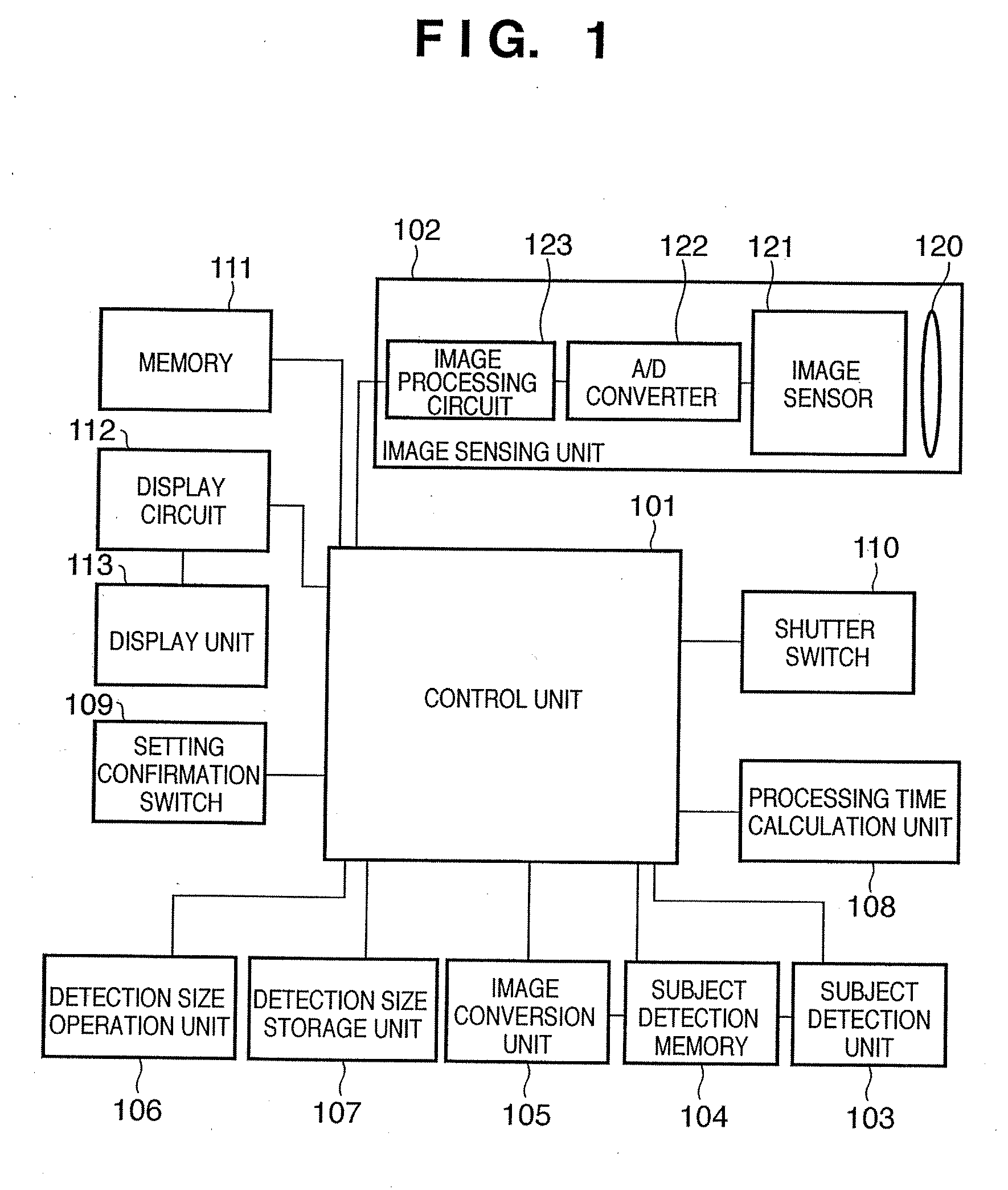
[0041]FIG. 1 is a diagram showing a configuration of an image sensing apparatus according to the first embodiment. In FIG. 1, reference numeral 101 denotes a control unit; 102, an image sensing unit; 103, a subject detection unit; 104, a subject detection memory; 105, an image conversion unit; 106, a detection size operation unit; 107, a detection size storage unit; 108, a processing time calculation unit; 109, a setting confirmation switch; 110, a shutter switch; 111, a memory; 112, a display circuit; and 113, a display unit.
[0042] The control unit 101 is a unit for controlling the entire image sensing apparatus. To the control unit 101, the image sensing unit 102, the subject detection unit 103, the subject detection memory 104, the image conversion unit 105, the detection size operation unit 106, the detection size storage unit 107, the processing time calculation unit 108, the setting confirmation switch 109, the shutter switch 110, the memory 111, and ...
second embodiment
[0093] [Second Embodiment]
[0094] Next, the second embodiment of the present invention will be described.
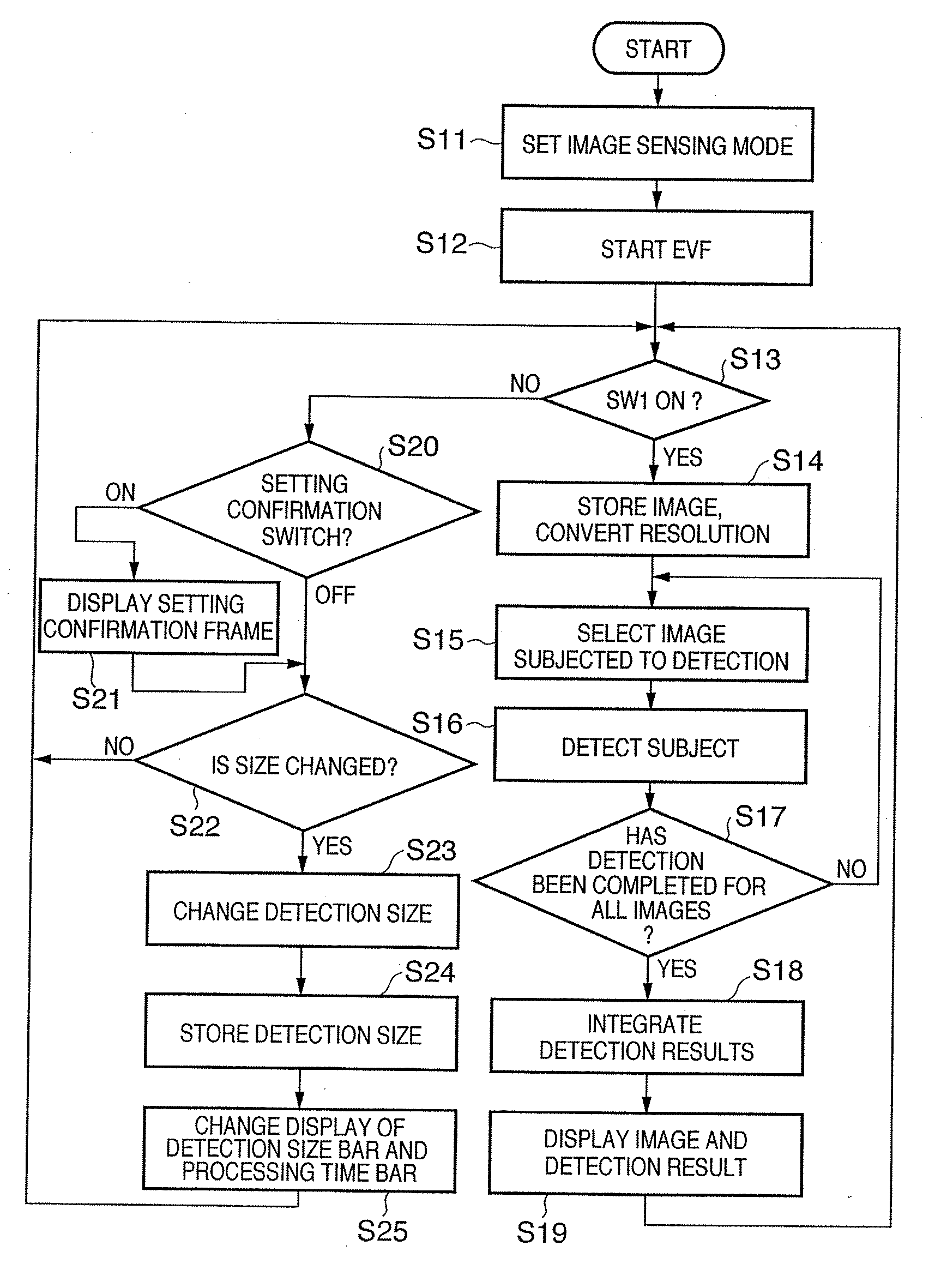
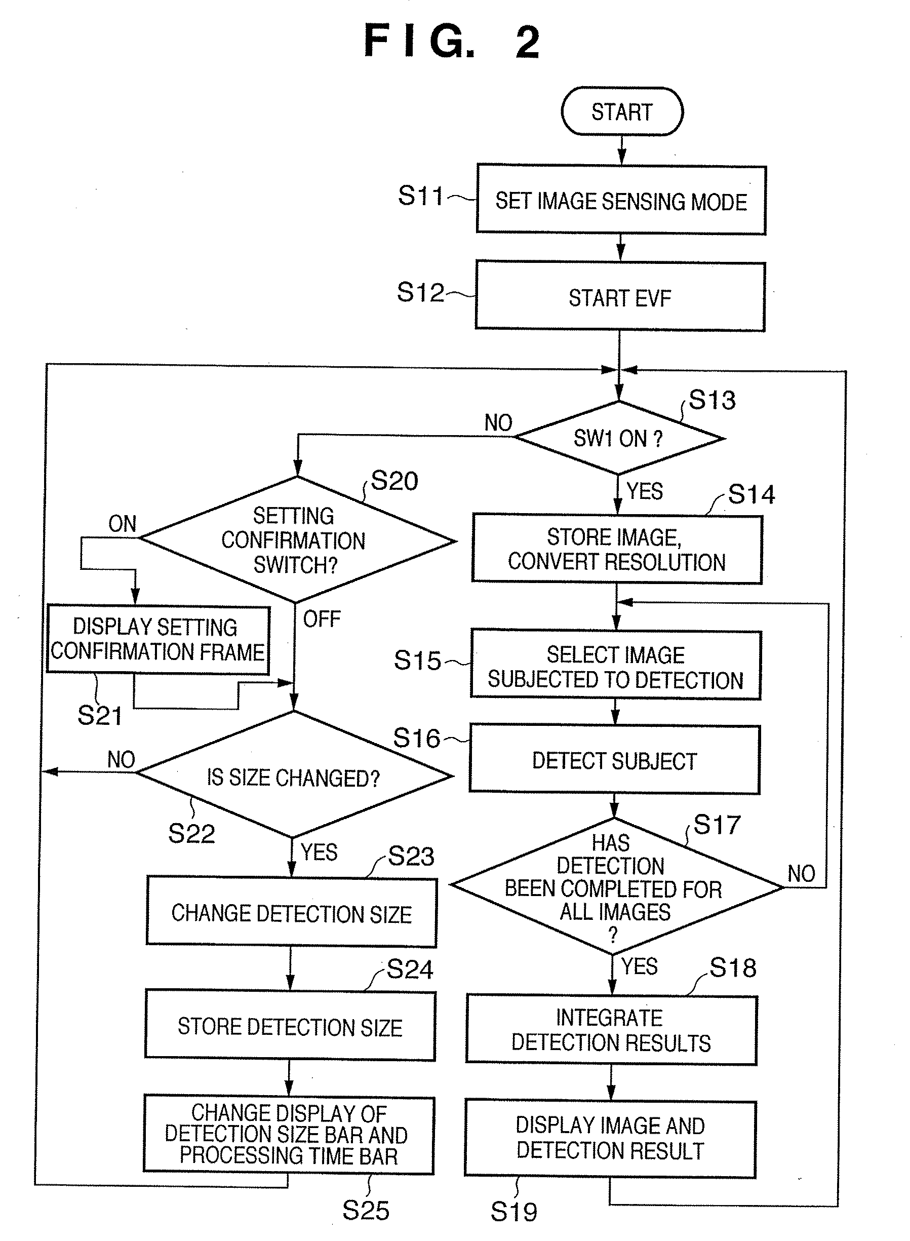
[0095] In this second embodiment, the resolution conversion, which is performed by the image conversion unit 105 in the first embodiment, is performed with a fixed resolution. In other words, mainly, in this second embodiment, the process at step S14 of the flowchart shown in FIG. 2 is different from that of the first embodiment. Since other processes and the configuration of the image sensing apparatus are similar to those described in the first embodiment, the description thereof is omitted here.
[0096] Hereinafter, the resolution conversion process performed at step S14 in the second embodiment will be described with reference to a flowchart shown in FIG. 9.
[0097] In the second embodiment, at step S14, three processes of creating the pyramid images, calculating a necessary detection resolution, and storing an image selection are performed.
[0098] First, at step S31, the resol...
third embodiment
[0110] [Third Embodiment]
[0111] Next, the third embodiment of the present invention will be described.
[0112] In the third embodiment, if a zoom control is performed, the detection size is automatically changed in proportion to its zoom amount.
[0113]FIG. 11 is a block diagram showing the configuration of an image sensing apparatus according to the third embodiment. In FIG. 11, the configuration similar to FIG. 1 is referred to by the same reference numeral, and the description thereof is omitted. In comparison to the configuration shown in FIG. 1, a zoom operation unit 314 has been added. By operating this zoom operation unit 314, the image sensing lens 120 in the image sensing unit 102 is controlled to change a zoom magnification.
[0114] Next, with reference to a flowchart of FIG. 12, the subject detection operation including the operation on the zoom operation unit 314 will be described. The process shown in FIG. 12 is basically controlled by the control unit 301. It should be no...
PUM
 Abstract
Description
Claims
Application Information