

In-folding motorcycle foot rests
a foot rest and motorcycle technology, applied in the field of in-folding motorcycle foot rests, can solve the problems of heavy, bulky highway pegs, and difficulty in braking and gear shifting, and achieve the effect of safety and comfor
- Summary
- Abstract
- Description
- Claims
- Application Information
AI Technical Summary
Benefits of technology
Problems solved by technology
Method used
Image

Examples
example
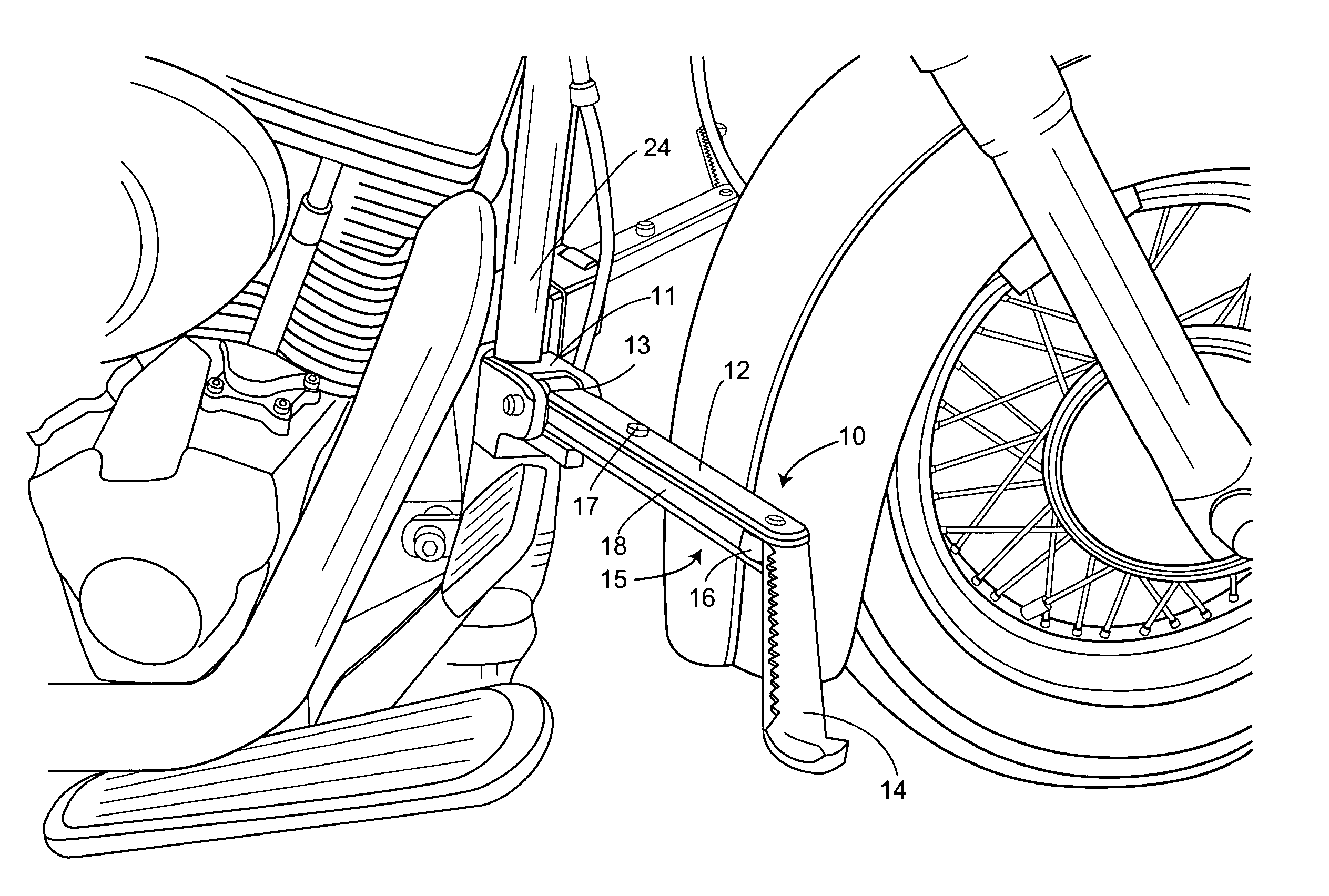
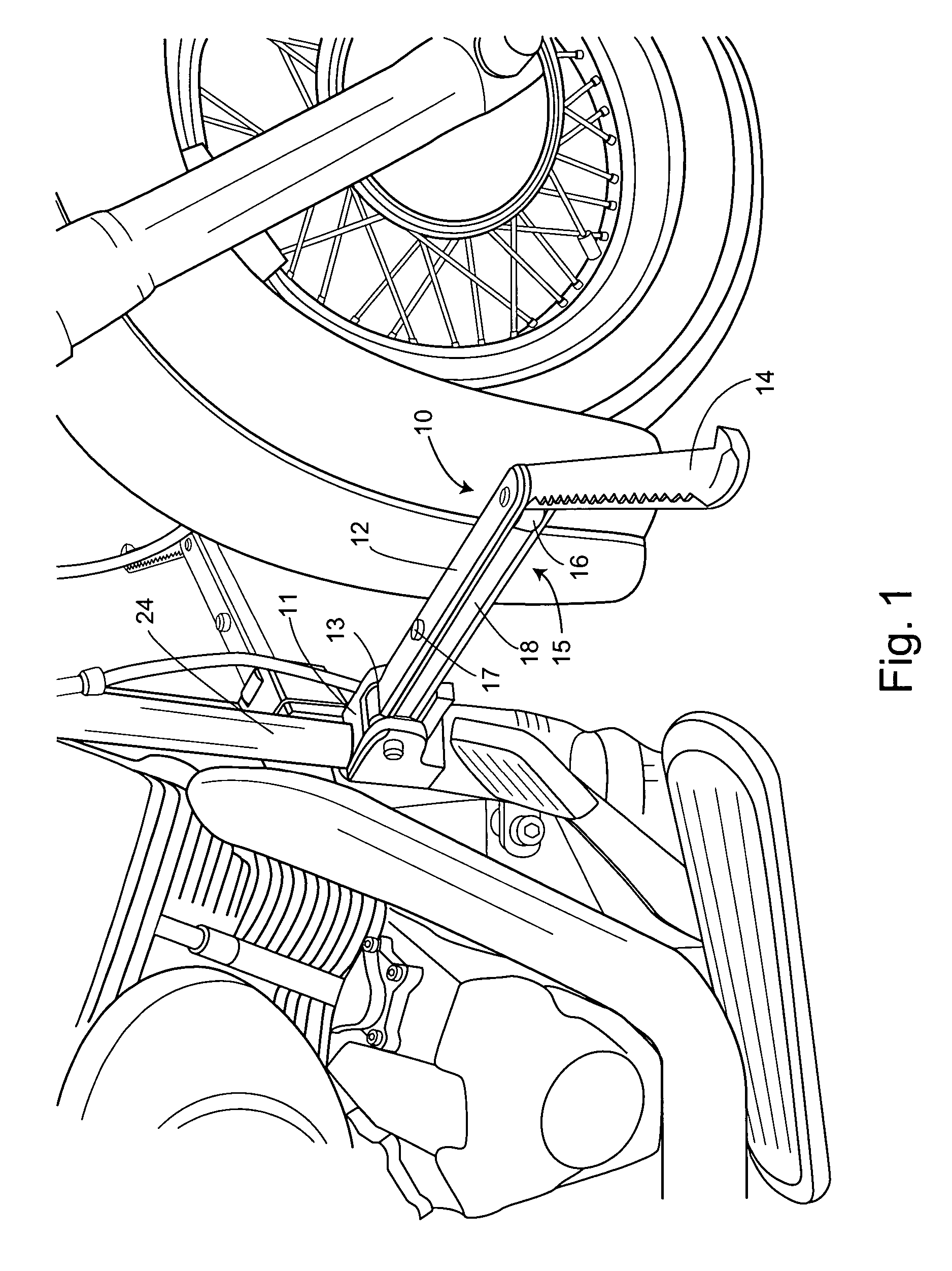
The Highway Blade
[0052] The following examples are offered to illustrate, but not to limit the claimed invention.
[0053] In-folding motorcycle foot rests were fabricated from tool steel to include a clamp type mounting bracket 40, an inner pivotable mount 41 having a pin-in-slot mechanism, an inner arm 42 featuring a push button release 43, an outer pivotable mount 44 for attachment of outer arm 45, as seen from above deployed in FIG. 4.
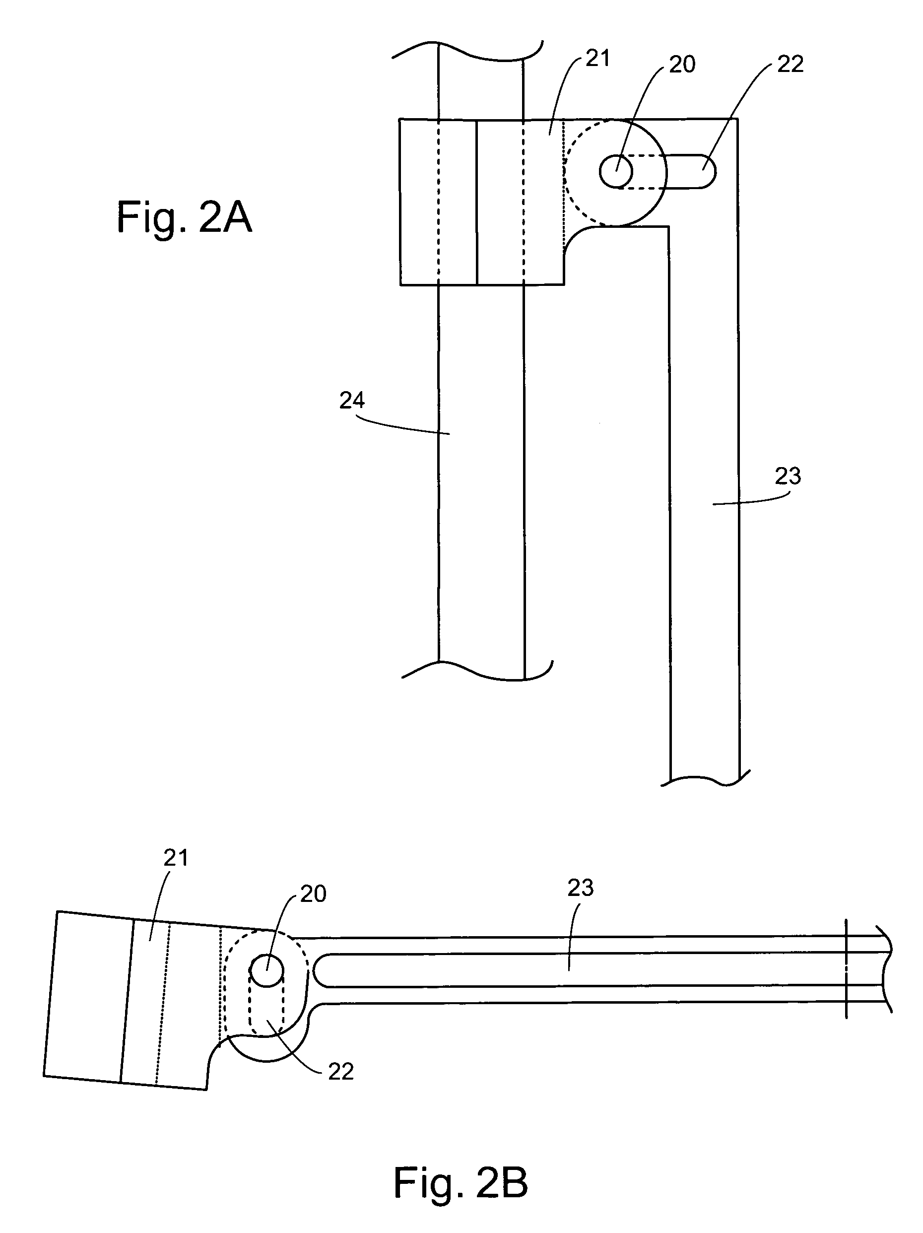
[0054] The mounting bracket can be clamped onto tubular front frame members at any inner angle 30 relative to a line 31 parallel to the longitudinal axis 46 of a motorcycle. This angle can be adjusted (repositioned) by simply loosening the clamp and pivoting the mounting bracket about the axis of the frame tube 24. The height of the entire foot rest can be adjusted (repositioned) by simply loosening the bracket clamp and sliding the bracket up or down the frame tube.
[0055] The inner arm 42 is mounted to the mounting bracket using a pin-in-slot mec...
PUM
 Abstract
Description
Claims
Application Information