

Projection image display apparatus and multi-projection system
a technology of projection image and display apparatus, applied in the field of projection image display apparatus and multi-projection system, can solve the problems of image and another image projected by another projector that may overlap with each other, and cannot be moved freely,
- Summary
- Abstract
- Description
- Claims
- Application Information
AI Technical Summary
Problems solved by technology
Method used
Image

Examples
embodiment 1
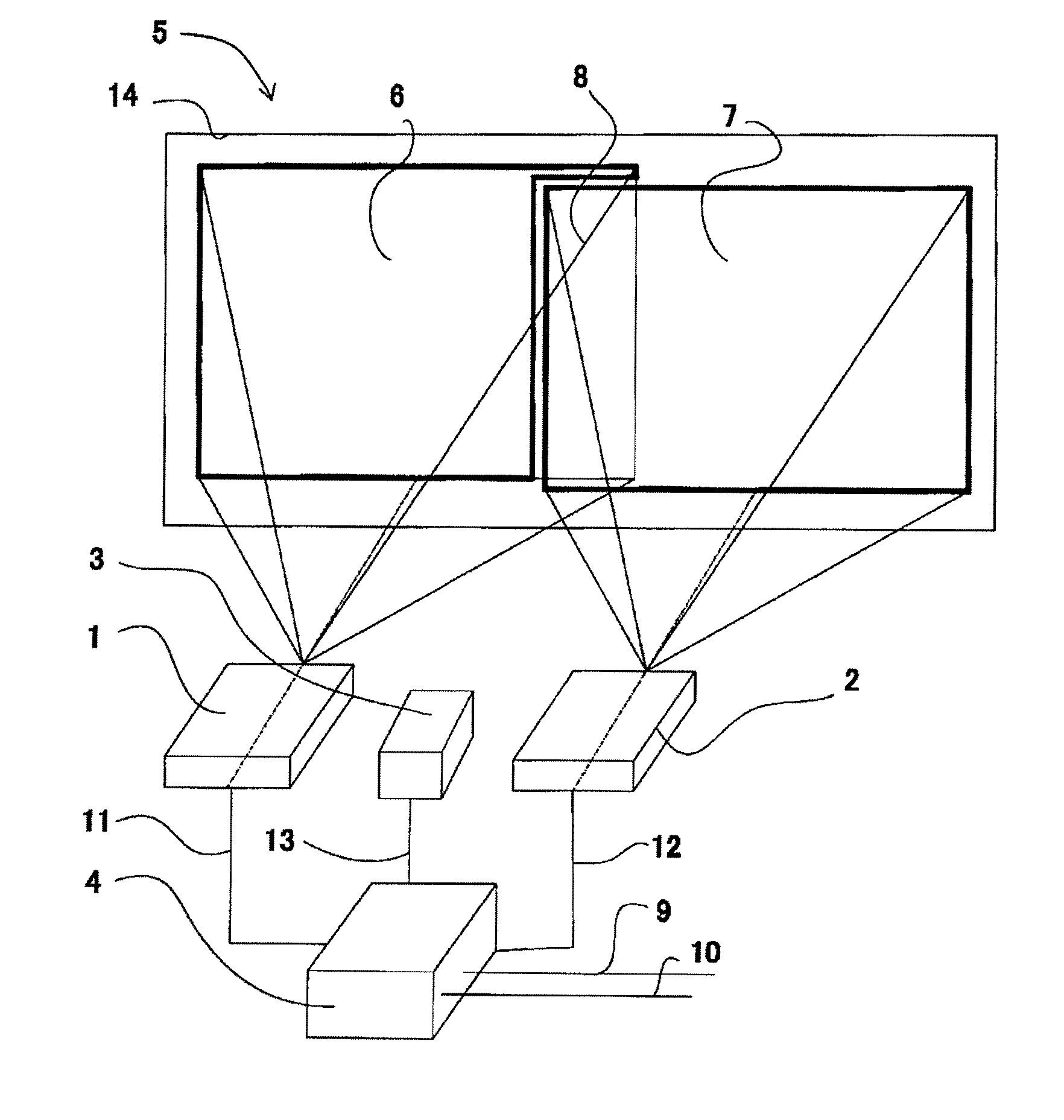
[0026]FIG. 1 is an outline view showing the configuration of the main part of the multi-projection system that is Embodiment 1 of the present invention.
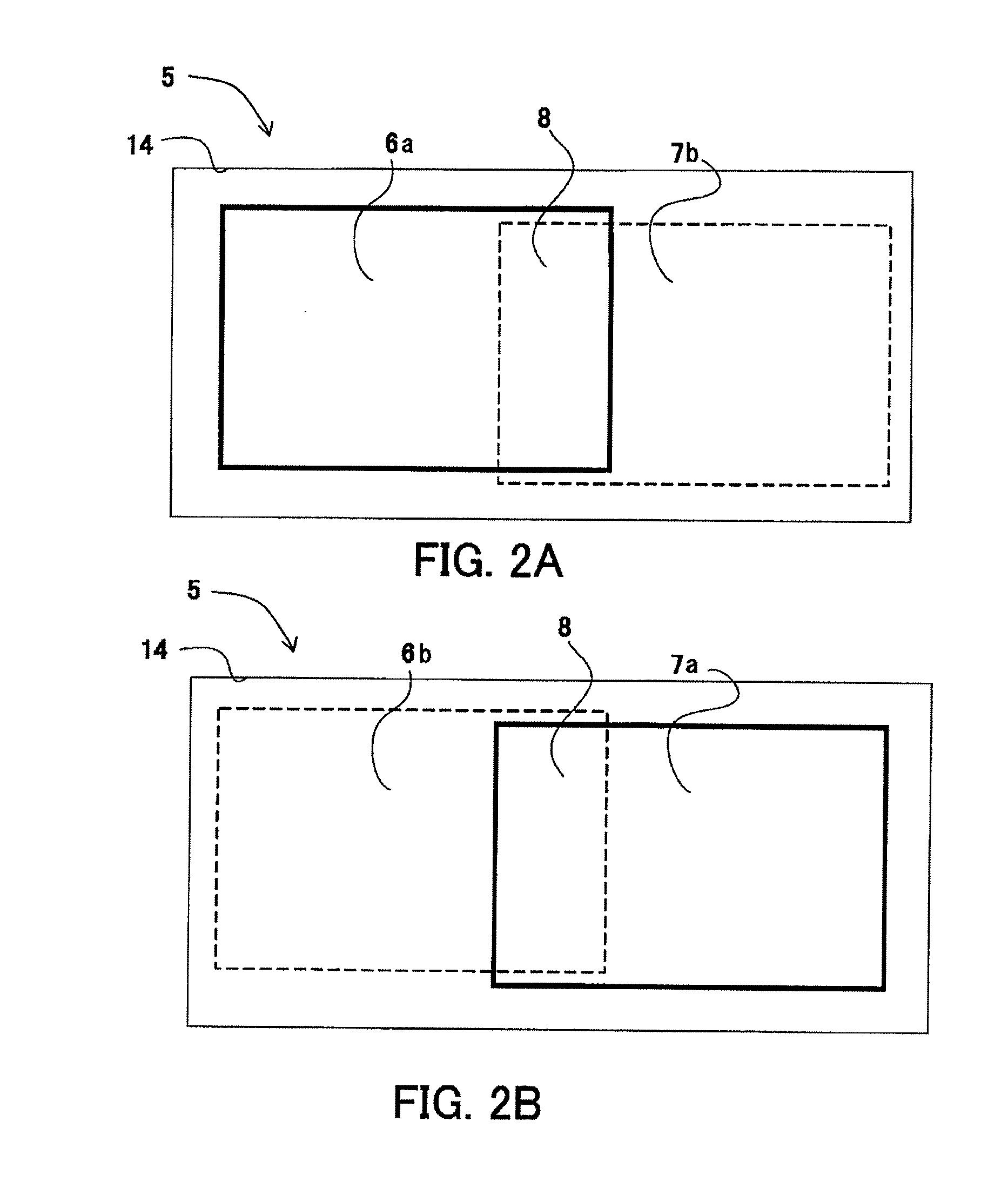
[0027] A first projector 1 and a second projector 2 respectively project images (video images) onto projection areas 6 and 7 of a screen (projection surface) 5. Video input signals 9 and 10 are signals based on images to be displayed by the projectors 1 and 2.
[0028] The projection areas 6 and 7 corresponding to the projectors 1 and 2 form an overlap area 8. Therefore, when the projectors 1 and 2 project the images based on the video input signals 9 and 10 onto the screen 5, the images overlap with each other in the overlap area 8, resulting in making it hard to recognize the images.
[0029] The video input signals 9 and 10 are input to a projection area controller 4 and converted into video input signals 11 and 12 whose projection areas are controlled by the controller 4. The video input signals 11 and 12 are input to the projectors...
embodiment 2
[0061]FIG. 5 is an outline view showing the configuration of the multi-projection system that is Embodiment 2 of the present invention. In FIG. 5, first and second projectors 15 and 16 respectively project images onto projection areas 20 and 21 on a screen 19.
[0062] Video signals 23 and 24 are input to the projectors 15 and 16, respectively. A projection area detector 17 detects information on an image 20 projected in a predetermined detection area 25 on the screen 19 by the first projector 15.
[0063] A projection area controller 18 is built in the main body of the first projector 15 and inputs a video signal generated by adding area-control to the video input signal 23 based on the detection result by the projection area detector 17. The projector 15 displays the image on the screen 19, based on the video signal.
[0064] A video input signal is input to the second projector 16 as it is, in other words, without control of the projection area.
[0065] The projection areas 20 and 21 co...
embodiment 3
[0095]FIG. 10 is an outline view showing the configuration of the multi-projection system that is Embodiment 3 of the present invention.
[0096] In FIG. 10, first and second projectors 26 and 32 respectively project images onto projection areas 35 and 34 on a screen 36.
[0097] The projector 26 is electrically connected to the projection area detector 27 and the projection area controller 30.
[0098] The projector 26 is a projector for a large screen, which projects a video image based on a video input signal 31 onto the screen 36.
[0099] On the other hand, the projector 32 is a small-sized portable projector which displays a video image based on a video input signal 33. The projection area 34 of the portable projector 32 is included in, in other words, completely overlapped with a projection area 35 of the projector 26.
[0100] A projection area detector 27 detects an image (projection area 35) in a detection area 37 on the screen 36. The projector 26 receives a video input signal 28 w...
PUM
 Abstract
Description
Claims
Application Information