Methods and apparatus for back-projection and forward-projection

a technology of forward projection and back projection, applied in the field of digital data processing, can solve the problems of limited applicability high computational costs, and high cost of prior art solutions for determining back projections, and achieve the effect of fewer computational resources and faster performan

Active Publication Date: 2005-07-14
PME IP
View PDF31 Cites 109 Cited by
  • Summary
  • Abstract
  • Description
  • Claims
  • Application Information

AI Technical Summary

Benefits of technology

[0009] Related objects of the invention are to provide such apparatus and methods as can be performed more rapidly and with fewer computational resourc...

Problems solved by technology

Though prior art solutions have proven effective in this regard, they are typically quite expensive.
Moreover, those prior art solutions for determining back-projections have limited applicability to a new class of imaging, referred to as tom...

Method used


Image

  • Methods and apparatus for back-projection and forward-projection
  • Methods and apparatus for back-projection and forward-projection
  • Methods and apparatus for back-projection and forward-projection

Examples


Embodiment Construction

[0024] The invention provides improved methodologies and apparatus for forward-projection and back-projection that reduce the time and processing power required to reconstruct three-dimensional volumetric representations, e.g., from a series of two-dimensional measured projection images.

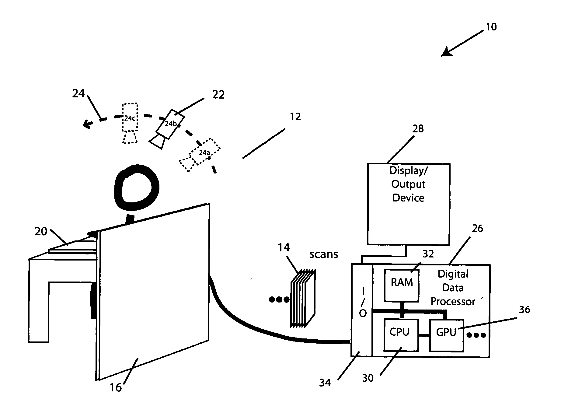
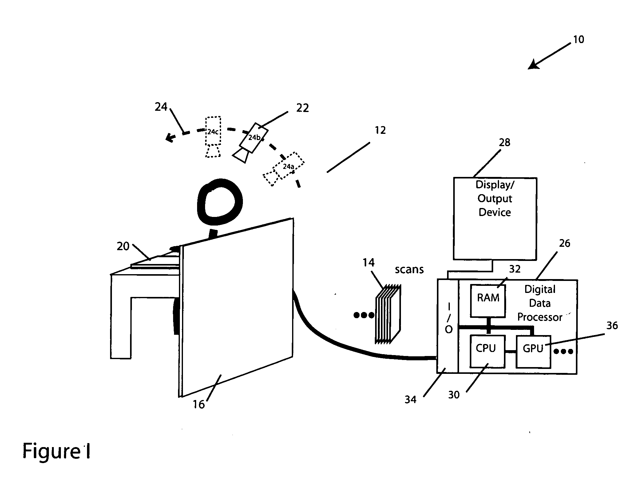
[0025] The invention has application, for example, in medical imaging and the embodiment described below is one such application: a tomosynthesis mammography system, which is based on maximum likelihood estimation maximization (MLEM) algorithm. It will be appreciated that the improved forward-projection and back-projection methodologies and apparatus described herein have application in computed tomography (CT), positron emission tomography (PET), single photon emission computed tomography (SPECT), and other medical imaging applications, as well as in reconstruction applications outside the medical realm, whether based on MLEM or otherwise.

[0026] Turning to the illustrated embodiment, FIG. 1 depict...


PUM


Abstract

The invention provides improvements in reconstructive imaging of the type in which a volume is reconstructed from a series of measured projection images (or other two-dimensional representations) generated by projection of a point x-ray source (or other radiation source), positioned at a distinct focus, through the volume to a plane at which the respective projection image is acquired (“detector plane”). In one aspect, the improvements are with respect to back-projecting a two-dimensional representation lying in the detector plane (representing, for example, a difference between an originally-acquired measured projection image and a subsequently-generated estimate thereof) to generate three-dimensional representation (which can be used, for example, to update an estimate of the volume). According to this aspect, for each of one or more slices of the 3D representation parallel to the projection plane and for each distinct focus at which a projection is generated, the following steps are performed in connection with the back-projection: (i) warping the first 2D representation to generate a second 2D representation by applying to the first 2D representation a selected linear mapping, where that selected linear mapping would map, in order to match dimensions of the respective slice within the 3D representation, a region defined by projection, at the respective focus, of comers of that slice onto the detector plane, and (ii) incrementing values of each of one or more voxels of the respective slice by an amount that is a function of a value of a correspondingly indexed pixel of the second 2D representation. A related aspect provides improvements with respect to forward-projecting, as well as in iterative (and non-iterative) methodologies that incorporate both back-projection and forward-projection.

Description

BACKGROUND OF THE INVENTION [0001] The invention relates to digital data processing and, particularly, to novel methods and apparatus for forward-projection and back-projection for use, e.g., in reconstructive imaging. The invention has application in health care and, specifically, medical imaging—as well as in a host of other areas, such as manufacturing, security, research, and defense. [0002] A forward-projection is an operation for estimating the (two-dimensional) transmission or emission shadow that would result from illumination of a (three-dimensional) object by a point source which emits radiation that partially passes through the object. By way of example, a forward-projection could be performed in order to provide an estimate of what an x-ray image of a human might look like. The term forward-projection also refers to the estimate that is determined from executing a forward-projection operation. [0003] A back-projection is an operation for generating a simple estimate of t...

Claims


Application Information

Patent Timeline
IPC IPC(8): A61B6/00A61B10/00G01N23/00G06F17/00G06K9/00G06K9/32G06K9/36G06T11/00G21K1/12H05G1/60
CPCG06T11/006Y10S128/922G06T2211/424
Inventor THIERET, SCOTT A.KOTLOV, VALERIGODDARD, JOSEPHBERMAN, ARI P.
Owner PME IP
Why Eureka
Try Eureka