

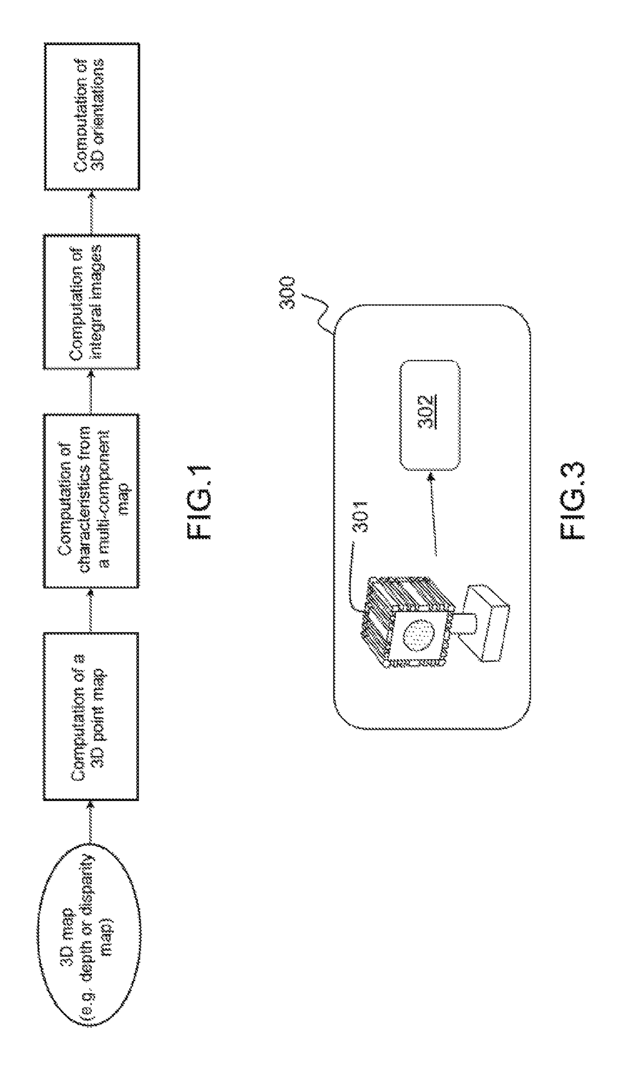
Method for characterising a scene by computing 3D orientation
a 3d orientation and scene technology, applied in the field of 3d orientation computation, can solve the problems of limiting the use of orientations to applications, the cost of these systems is high (one or more thousands of dollars), and the use of orientations is wrongly considered to be limited to these applications
- Summary
- Abstract
- Description
- Claims
- Application Information
AI Technical Summary
Benefits of technology
Problems solved by technology
Method used
Image

Examples
Embodiment Construction
[0049]A depth map or disparity map is an (orthogonal or perspective) projection of 3D space onto a 2D plane. The result of this projection causes a partial loss of the notion of 3D vicinity between elements of the scene. As existing solutions rely on integral images, the local characteristics are systematically computed from 2D media (rectangular zones of the 2D image). These zones may contain a plurality of elements of the scene that are not necessarily close to one another. In these cases, substantial errors caused by the 2D vicinity corrupt the characteristics and particularly penalize the computation of 3D orientation.
[0050]Direct processing of the 2D image may allow certain characteristics of the initial scene to be determined, provided that additional information is provided or additional processing carried out.
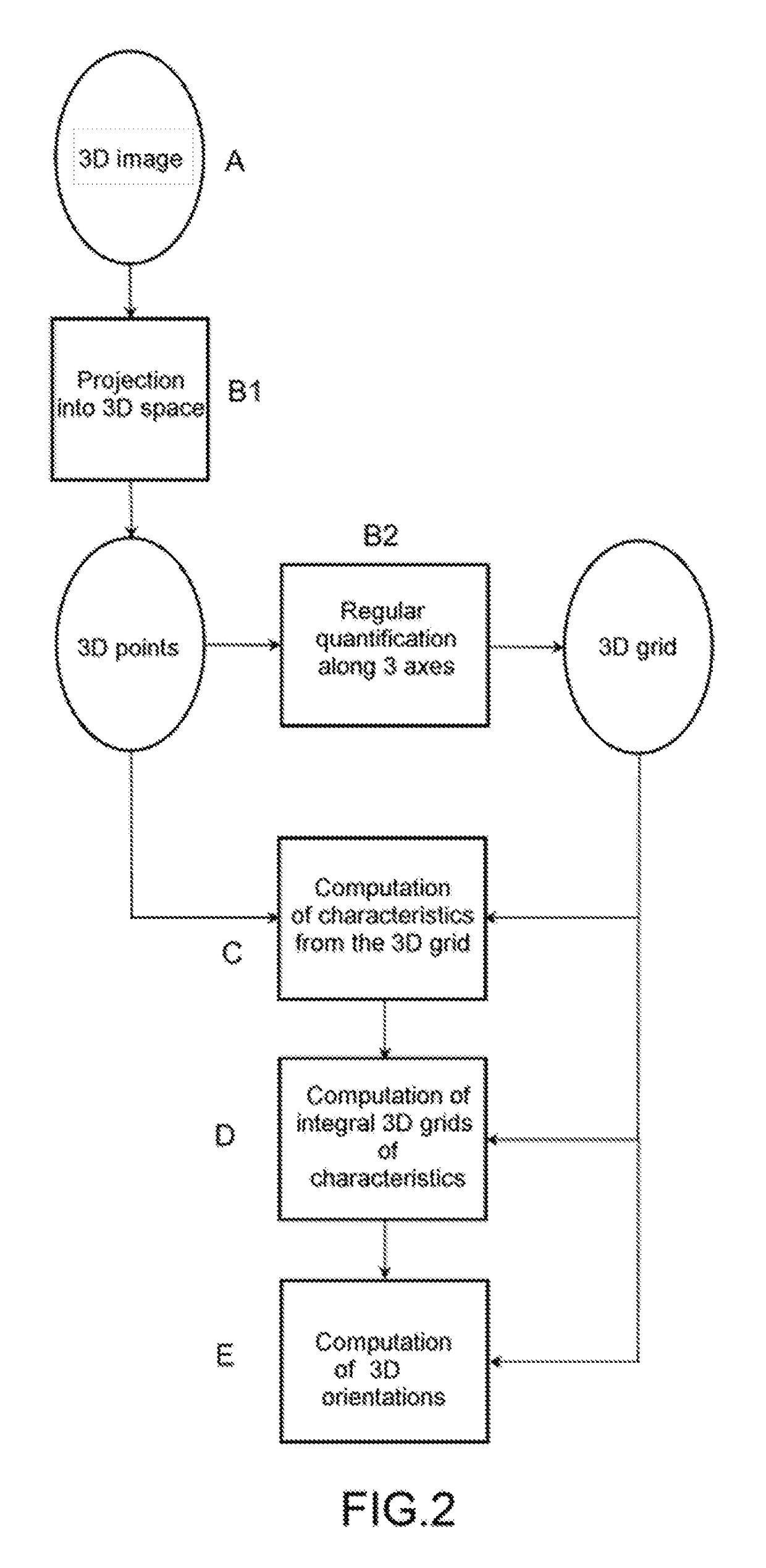
[0051]However, the only way of determining local 3D characteristics precisely is to consider real space, which is of three-dimensional nature. Knowledge of the actual v...
PUM
 Abstract
Description
Claims
Application Information