Trace optimization in flattened netlist by storing and retrieving intermediate results

a netlist and optimization technology, applied in the field of netlist tracing, can solve the problems of duplicate efforts of conventional tracing applications, and achieve the effect of reducing processing time and fewer computational resources

a netlist and optimization technology, applied in the field of netlist tracing, can solve the problems of duplicate efforts of conventional tracing applications, and achieve the effect of reducing processing time and fewer computational resources

US20080229268A1Active Publication Date: 2008-09-18BELL SEMICON LLC

Image

  • Trace optimization in flattened netlist by storing and retrieving intermediate results
  • Trace optimization in flattened netlist by storing and retrieving intermediate results
  • Trace optimization in flattened netlist by storing and retrieving intermediate results

Examples


Embodiment Construction

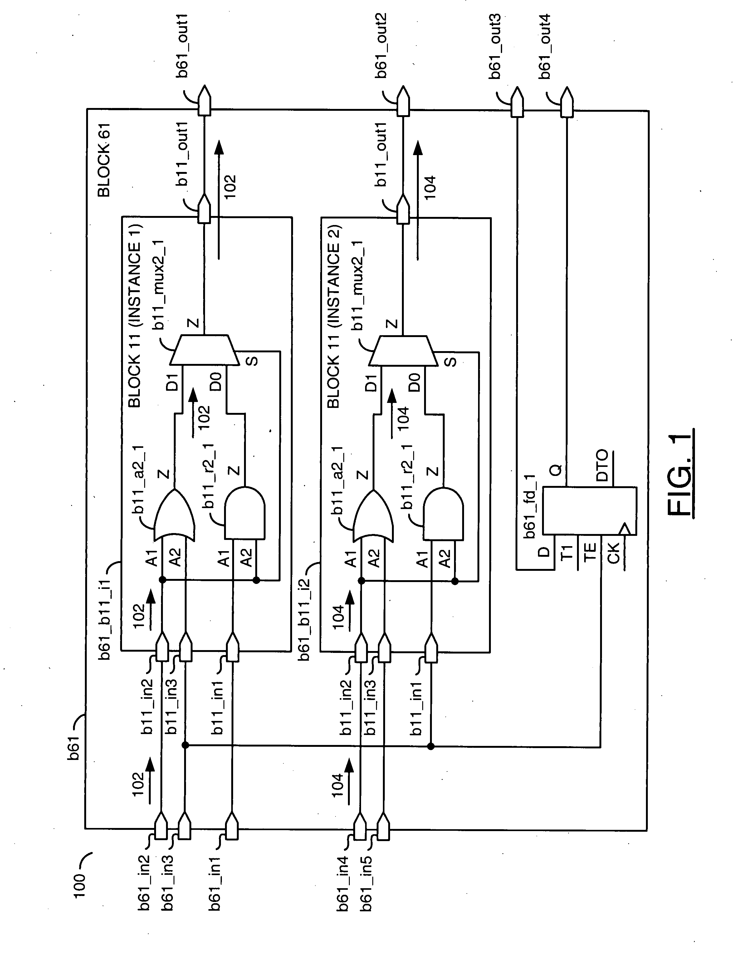
[0014]Referring to FIG. 1, a block diagram of an example circuit 100 being evaluated is shown. The circuit 100 may be designated as a block (e.g., BLOCK 61 or b61) at a particular level of a hierarchical netlist of the circuit 100. The block b61 generally comprises a first block (or module), a second block (or module) and a third block (or module). The first module, the second module and the third module may reside at a next lower level in the hierarchical netlist of the circuit 100. In the example show, the first module and the second module may be copies of a particular block (e.g., BLOCK 11 or b11). Hence, the first module may be a first instance (e.g., i1) of the block b11 and thus designated as b61_b11_i1. The second module may be a second instance (e.g., i2) of the block b11 and thus designated as b61_b11_i2. The third module may be a unique module (e.g., fd_1) and thus designated as b61_fd_1.

[0015]The block b61 may have one or more input ports (e.g., b61_in1 through b61_in5) ...


PUM


Abstract

A method of trace optimization in a flattened netlist of a circuit is disclosed. The method generally includes the steps of (A) generating a first total result by tracing a first path through the flattened netlist, (B) writing an intermediate result in a memory, the intermediate result characterizing a module having a plurality of instances in the circuit, (C) adding the intermediate result as read from the memory to the first total result upon crossing each of the instances of the module along the first path and (D) writing the first total result into the memory.

Description

FIELD OF THE INVENTION [0001]The present invention relates to netlist tracing generally and, more particularly, to trace optimization in flattened netlists by storing and retrieving intermediate results.BACKGROUND OF THE INVENTION [0002]Tracing a hierarchical netlist is a popular routine used in conventional Electronic Design Automation (EDA) applications. Conventional netlist tracing applications analyze a circuit by stepping along a path through the netlist from a starting point to an ending point. The analysis evaluates the circuit at each node along the path independently of any prior analyses performed at an earlier node. As a result, the conventional tracing applications often duplicate efforts when the path crosses several instances of a block of circuitry.SUMMARY OF THE INVENTION [0003]The present invention concerns a method of trace optimization in a flattened netlist of a circuit. The method generally comprises the steps of (A) generating a first total result by tracing a ...

Claims


Application Information

Patent Timeline
18 Sep 2008
Publication
US20080229268A1
IPC
G06F17/50
CPC
G06F17/5045; G06F30/30
Inventors
RANGASAMY, UMESH; ADIGA, SRINIDHI