Method, device, and system for computing a spherical projection image based on two-dimensional images

a projection image and coordinate system technology, applied in the field of methods, devices, systems for computing projection images based on spherical coordinate systems, can solve problems such as degrading visual and algorithmic performance, and presenting with very poor (anisotropic) resolution

Inactive Publication Date: 2014-11-20
LOGOS TECH
View PDF4 Cites 103 Cited by
  • Summary
  • Abstract
  • Description
  • Claims
  • Application Information

AI Technical Summary

Problems solved by technology

However, when such a high-resolution image is generated that is projected to an orthographic coordinate system, portions of the image far from the center of projection compared to an altitude of the capturing sensor will be presented with very poor (anisotropic) resolution due to the obliquity.
In addition, because a location of the source is often constantly moving, the image will have parallax motion which degrades a visual and algorithmic performance.

Method used


Image

  • Method, device, and system for computing a spherical projection image based on two-dimensional images
  • Method, device, and system for computing a spherical projection image based on two-dimensional images
  • Method, device, and system for computing a spherical projection image based on two-dimensional images

Examples


Embodiment Construction

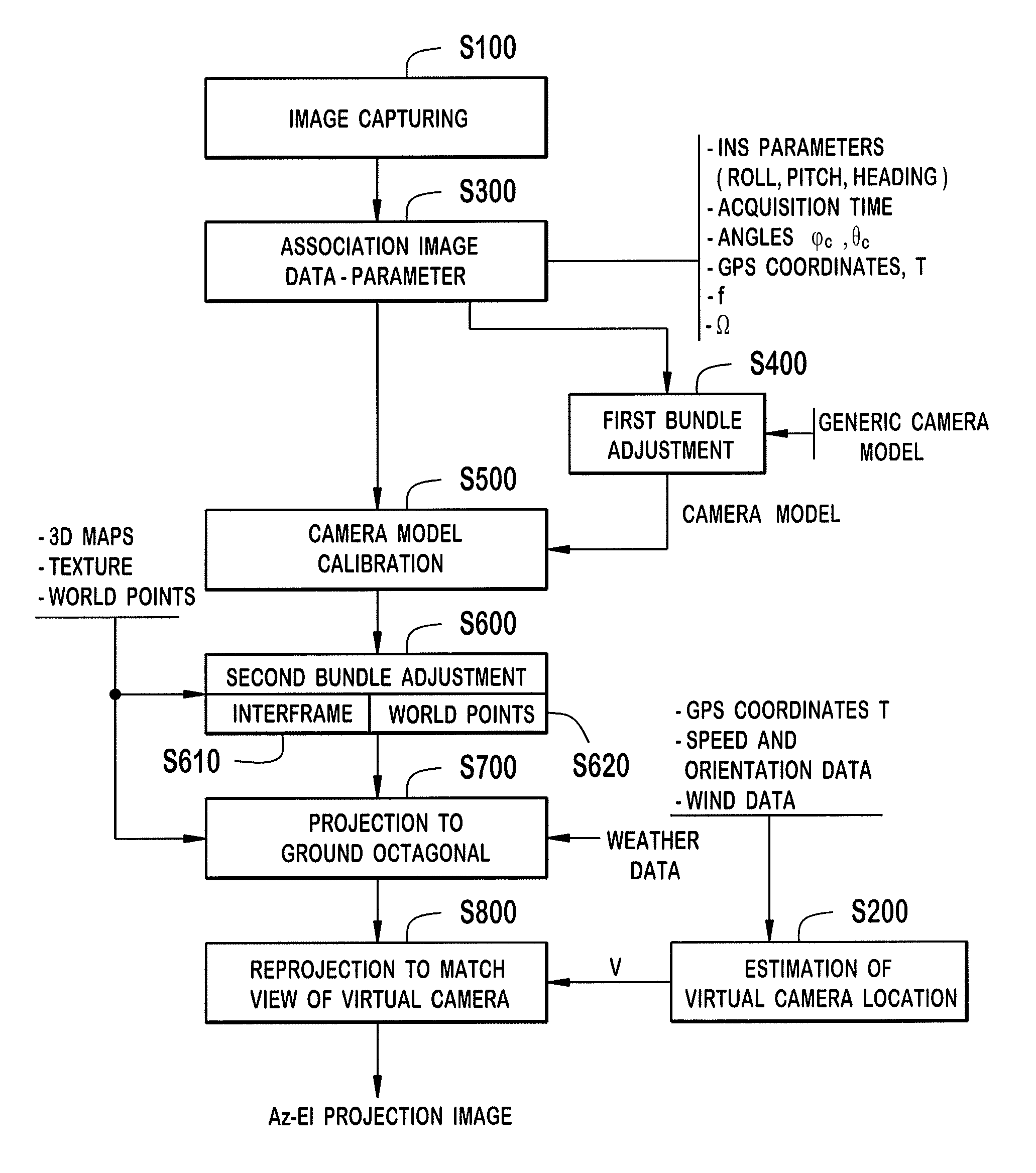
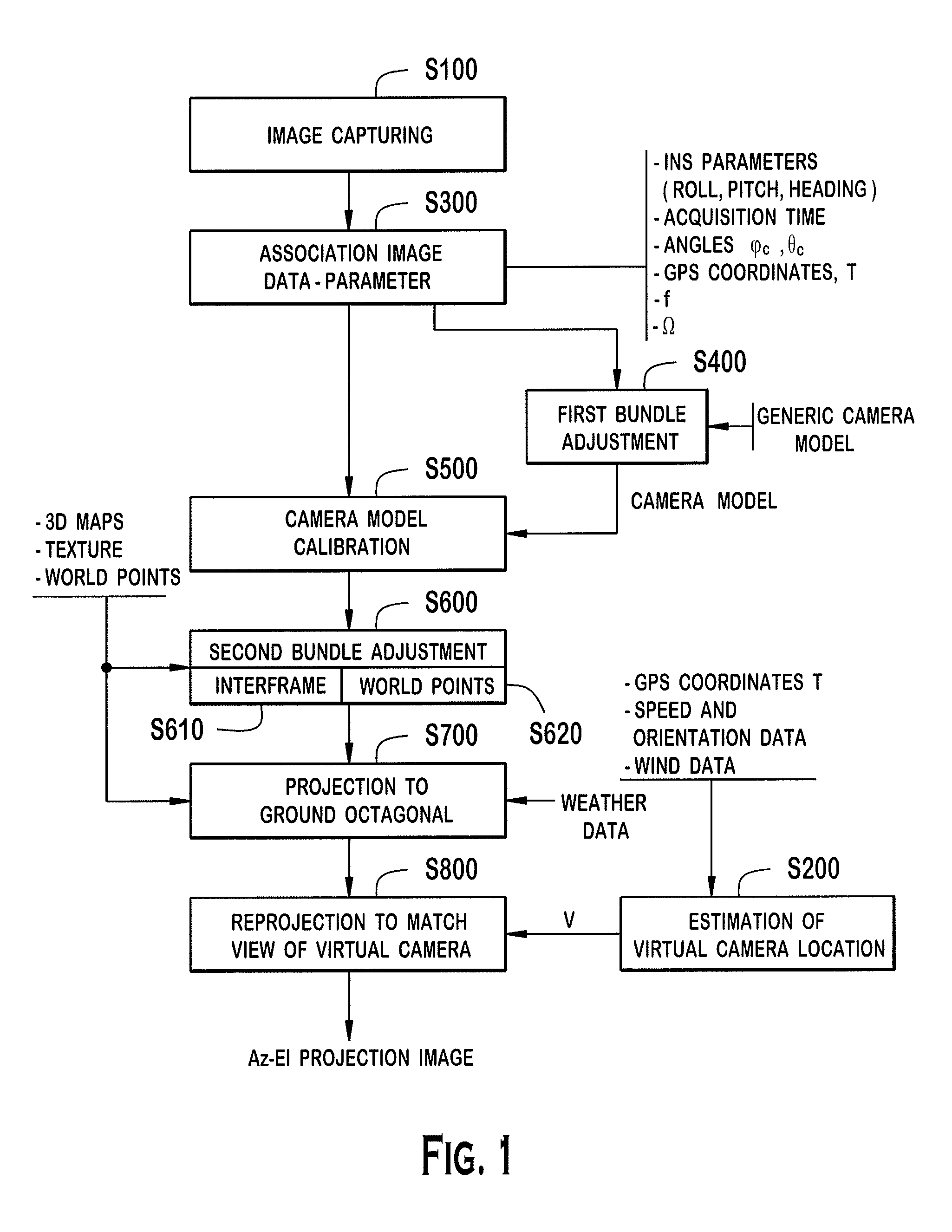
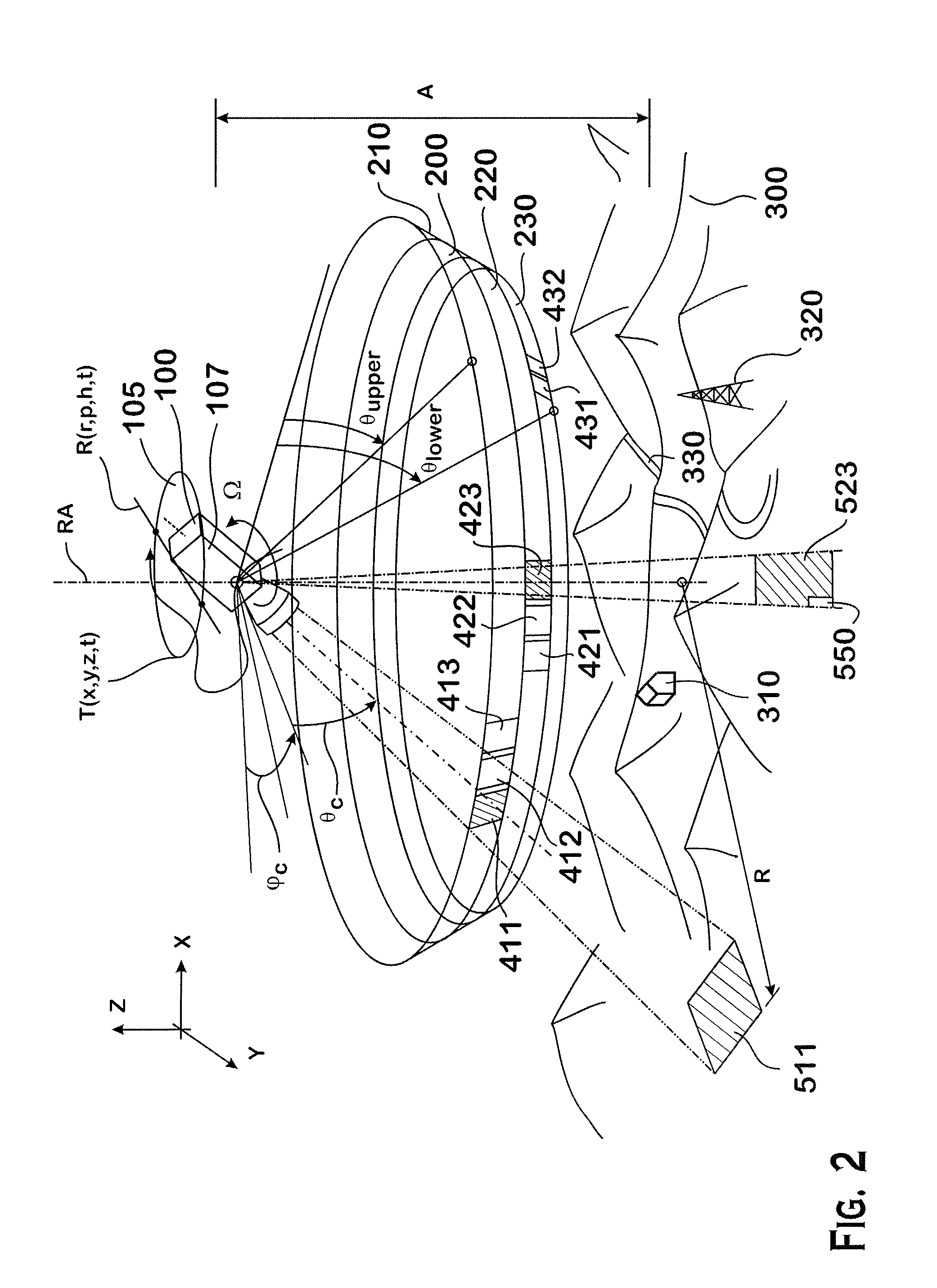
[0003]According to one aspect of the present invention, an image projection method for generating a panoramic image is provided, the method performed on a computer having a first and a second memory. Preferably, the method includes a step of accessing a plurality of images from the first memory, each of the plurality of images being captured by a camera located a source location, and each of the plurality of images being captured from a different angle of view, the source location being variable as a function of time, and calibrating the plurality of images collectively to create a camera model that encodes orientation, optical distortion, and variable defects of the camera. Moreover, the method further preferably includes the steps of matching overlapping areas of the plurality of images to generate calibrated image data having improved knowledge on the orientation and source location of the camera, accessing a three-dimensional map from the second memory, and first projecting pixe...


PUM


Abstract

An image projection method for generating a panoramic image, the method including the steps of accessing images that were captured by a camera located at a source location, and each of the images being captured from a different angle of view, the source location being variable as a function of time, calibrating the images collectively to create a camera model that encodes orientation, optical distortion, and variable defects of the camera; matching overlapping areas of the images to generate calibrated image data, accessing a three-dimensional map, first projecting pixel coordinates of the calibrated image data into a three-dimensional space using the three-dimensional map to generate three-dimensional pixel data, and second projecting the three-dimensional pixel data to an azimuth-elevation coordinate system that is referenced from a fixed virtual to generate the panoramic image.

Description

FIELD OF THE INVENTION[0001]The present invention relates generally to methods, devices, and systems for computing a projection image based on a spherical coordinate system by using two-dimensional images that were taken with different centers of projection.BACKGROUND OF THE INVENTION[0002]In imaging surveillance systems, for example for persistent surveillance systems, usually high resolution images are generated from a scenery by a camera system that can capture images from different viewing angles and centers of projection. These individual images can be merged together to form a high-resolution image of the scenery, for example a two or three-dimensional orthographic map image. However, when such a high-resolution image is generated that is projected to an orthographic coordinate system, portions of the image far from the center of projection compared to an altitude of the capturing sensor will be presented with very poor (anisotropic) resolution due to the obliquity. In additio...

Claims


Application Information

Patent Timeline
Patent Type & Authority Applications(United States)
IPC IPC(8): G06T5/50G06T3/00H04N13/239H04N13/243
CPCG06T5/50G06T2215/08G06T2207/20221G06T3/0068H04N9/3185G06T3/0062H04N13/243H04N13/246H04N13/207H04N13/363H04N13/239H04N23/698G06T7/38G06T17/05H04N5/2624H04N5/265H04N5/2628G06F16/29G06T2207/20212G06T2207/30232G06T2207/30181H04N23/951
Inventor BAKER, PATRICK TERRY
Owner LOGOS TECH
Why Eureka
Try Eureka