"Mdporta-lift" transportable, transformable, telescoping, leightweight, cantilevered trolley track, half ton capacity material conveying lift

a technology of conveying equipment and transportable trolleys, applied in the direction of transportation and packaging, load-engaging elements, cranes, etc., can solve the problems of limited utility, system additional weight, and much to heavy or bulky for one person to set up, so as to reduce the injury of workers and reduce the damage to the body long and short term.

Inactive Publication Date: 2007-03-15
DAMBROSEO MICHAEL FRANK
View PDF15 Cites 15 Cited by
  • Summary
  • Abstract
  • Description
  • Claims
  • Application Information

AI Technical Summary

Benefits of technology

[0036] It is another object of the invention to reduce worker injury, long and short term physical damage to workers and people lifting heavy objects.

Problems solved by technology

For example a given lifting apparatus would typically be limited to a single fixed installation location with a single method of attachment.
Other lifting apparatuses in existence have not been designed with interchangeable mounting adapters / elements for multiple methods of attachment, adjustability in height / width or do not have adaptability for using Both a mechanical or electromechanical hoist device and is likely lacking a jib type extended lift point beyond its structural framework or is much to heavy or bulky for one person to set up anywhere feasible.
Other devices typically have only one method of set up, i.e. on a flat roof with or with out a parapet wall, fixed in place or affixed to a standard or utility truck bed or are based on the use of a common runged extension ladder and as a result have limited utility etc, in comparison with the submitted invention of this application.
Other apparatuses may have hydraulics and or a gas engine included as part of their design, these systems are additional weight, increase purchase price, more maintenance etc.

Method used


Image

  • "Mdporta-lift" transportable, transformable, telescoping, leightweight, cantilevered trolley track, half ton capacity material conveying lift
  • "Mdporta-lift" transportable, transformable, telescoping, leightweight, cantilevered trolley track, half ton capacity material conveying lift
  • "Mdporta-lift" transportable, transformable, telescoping, leightweight, cantilevered trolley track, half ton capacity material conveying lift

Examples


Embodiment Construction

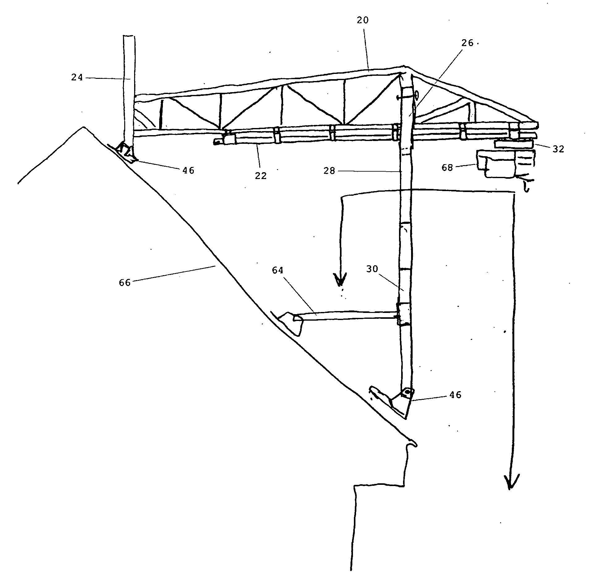
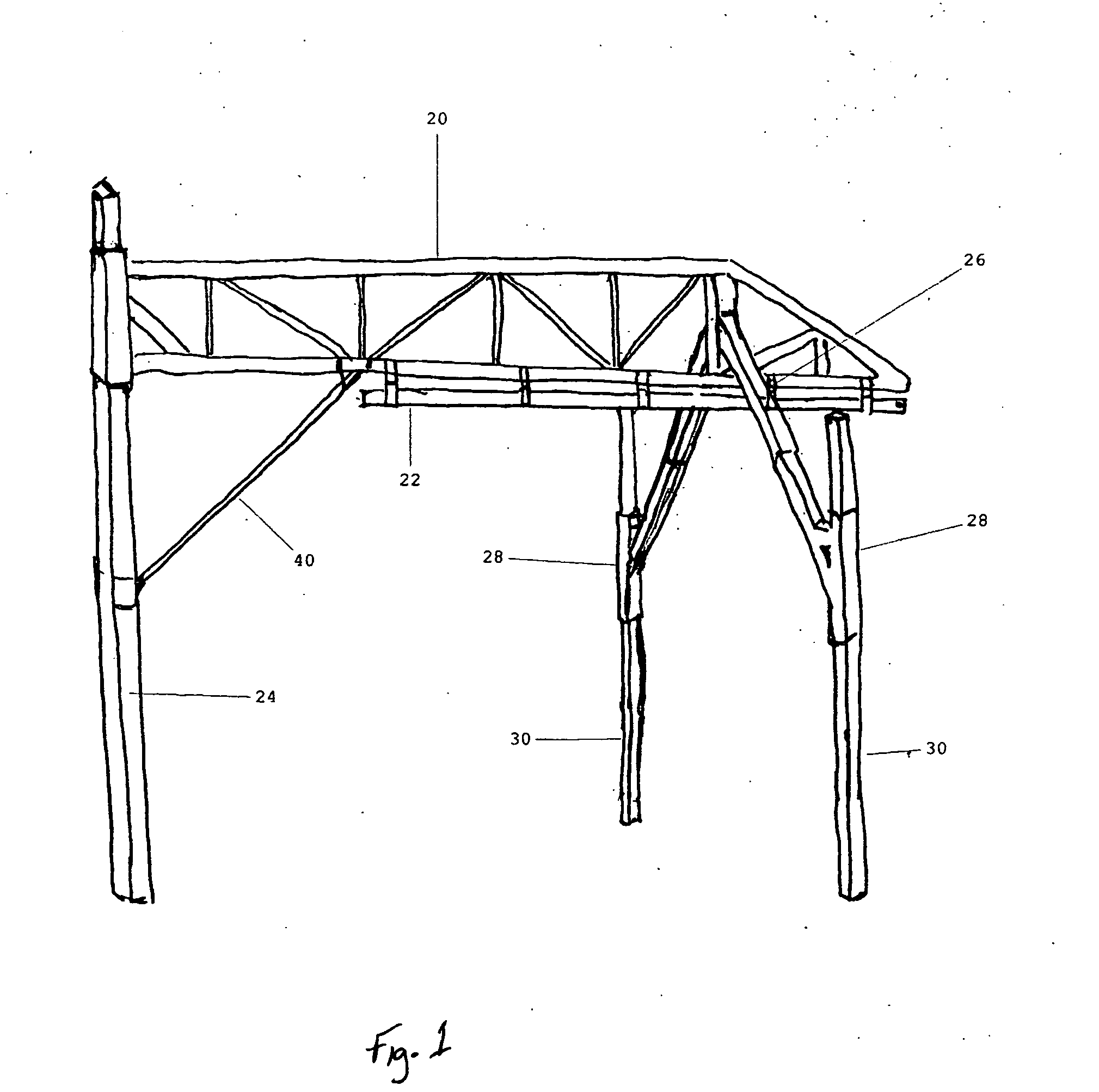
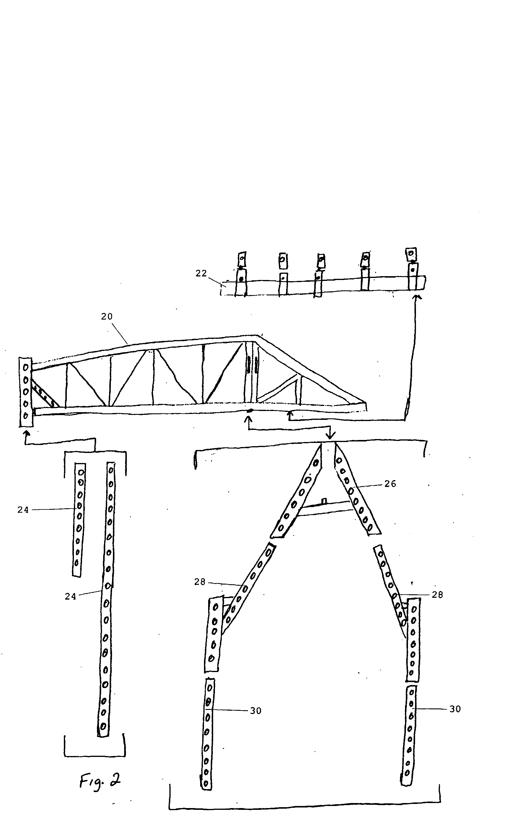
[0059]FIG. 1 is a perspective view of a convert-a-crane in accordance with the invention. An object and material lifting and moving device with almost unlimited set up configurations. Whereby installation and attachment is achieved by utilizing one of many combinations of accessory adapters. This invention is intended to lift; “transversely move back and forth (as on a trolley track); and set down the object(S) or material(S) from surface to surface i.e. ground to roof top; ground to vehicle or trailer bed; floor to elevated loft / storage area within a structure; from in or below water surface to boat deck or dock or any other conceived use like a large scale crane. The convert-a-crane can be constructed of many combinations of hollow or solid tubing's or any other suitable material whereby generally the main frame 20 and accessory adapters are welded fabricated and interchangeable with each other according to the connections diagram of this application, they are secured using a form...


PUM


Abstract

A “truss frame” lift apparatus having an “extended reach” beyond its supporting framework lifting capability which is supported by three legs. A lift that is welded fabricated from a combination of square tubing; telescoping square tubing; round hollow or round solid bar stock; ninety degree angle brackets; flat plate stock and several nuts and bolts, whereby multiple adapters are used to customize set up for use ranging from (steeply sloped to flat) roofs, vehicles, boats, decks, docks warehouses or any other conceived use where lifting and transferring from one elevation to another is required. This lift design provides means of use in a multitude of ways by assembling interchangeable components with locking pins to either front or rear leg(s). This lift is anchored or ballasted depending on method of set up at its rear support leg.

Description

FIELD OF THE INVENTION [0001] The present invention relates to material conveying apparatuses and, more particularly to one that can be quickly installed on a minimum surface area of three feet by seven feet on most any angled or flat surface (or combination of) whether mobile or fixed using one or a combination of special attachment adapters and can be used by one or more persons almost anywhere. BACKGROUND OF THE INVENTION [0002] The lack of a jib type lifting apparatus product that is a comparably functional replacement for fixed and mobile cranes, which is lightweight, quickly set up; detachably connected to its fixed, moveable or pivoting mounts and is convertible to almost unlimited setup requirements and locations; almost infinitely adjustable, in height and width; transportable, and that one average person can set up for use almost anywhere. More specifically this device design would require it to function so as to replicate the path of motion necessary to convey any object ...

Claims


Application Information

Patent Timeline
Patent Type & Authority Applications(United States)
IPC IPC(8): B66C1/02
CPCB66C23/205
Inventor DAMBROSEO, MICHAEL FRANK
Owner DAMBROSEO MICHAEL FRANK
Why Eureka
Try Eureka