Device and process for breath-supporting respiration

a technology of respiration and device, which is applied in the direction of valve details, valve arrangements, life-saving devices, etc., can solve the problems of continuous gas flow and compromise the measurement of the stroke volume applied only slightly, and achieve the effect of compromising the measurement of the stroke volume and closing pressur

Inactive Publication Date: 2007-03-22
DRAGERWERK AG
View PDF7 Cites 25 Cited by
  • Summary
  • Abstract
  • Description
  • Claims
  • Application Information

AI Technical Summary

Benefits of technology

This patent describes a method for controlling the amount of air patients receive during ventilation therapy. By measuring the pressure at different points in the breathing cycle, including just before they start to breathe (the pre-inspiratory phase), this system can adjust the level of air supply accordingly. When the patient tries to breath, the system increases the airflow to restore the original pressure levels. This allows for better synchronization with the patient's natural breathing pattern and reduces the risk of artificially inducing lung inflation or deflation. Overall, this technology ensures safe and effective ventilation therapy while minimizing discomfort for patients.

Problems solved by technology

The technical problem addressed in this patent relates to improving the accuracy and sensitivity of triggers used in respirators to detect and synchronize patient ventilation with mechanical breathing support. Current methods require relatively large amounts of continuous gas flow through the system, leading to increased costs and limitations in sensor precision. There is a need for more efficient and accurate techniques for controlling the timing and duration of mechanical ventilation in response to patient needs.

Method used


Image

  • Device and process for breath-supporting respiration
  • Device and process for breath-supporting respiration
  • Device and process for breath-supporting respiration

Examples


Embodiment Construction

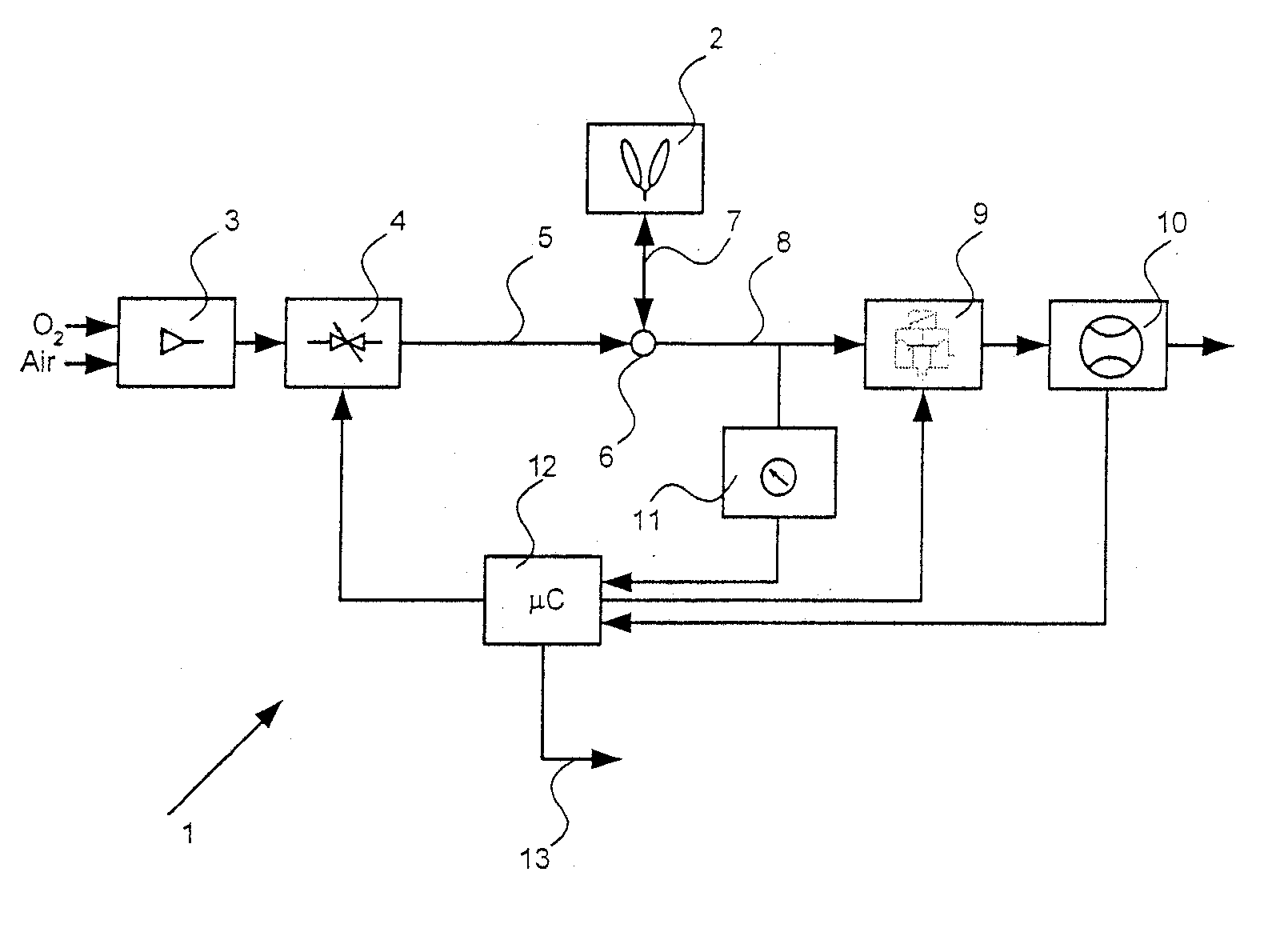
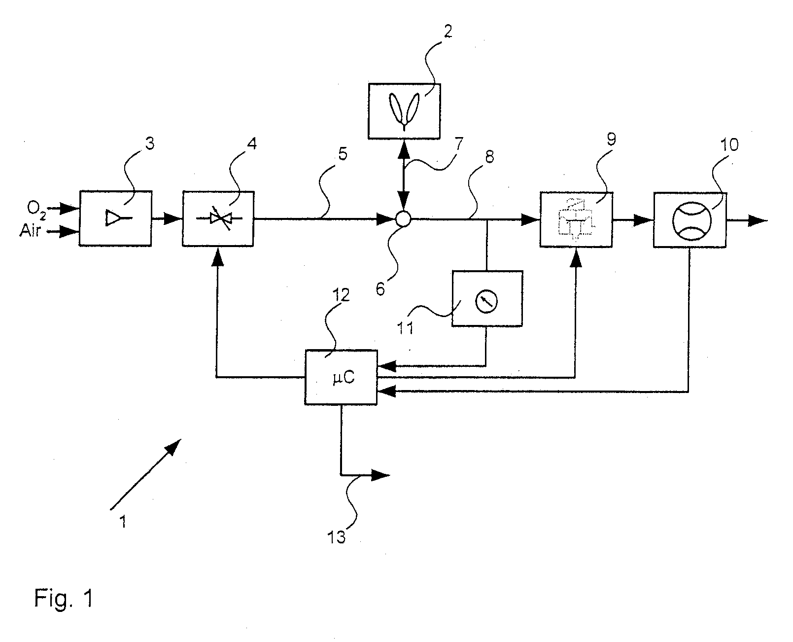
[0021] Referring to the drawings in particular, FIG. 1 illustrates a respirator 1 for supplying a patient 2 with breathing gas. A gas mixer 3, acting as a breathing gas source, generates a breathing gas mixture from oxygen (an oxygen source) and air. The breathing gas mixture enters an inspiration line 5 via a dispensing valve 4, which can be actuated and acts as a feed means. The inspiration line 5 is connected at a branching point 6 to a breathing gas line 7 leading to the patient (patient connection) 2 and to an expiration line 8. The expiration line 8 ends at an expiration valve 9. The gas flow of the expired gas is measured on the discharge side of the expiration valve 9 with a flow sensor 10. A pressure sensor 11 arranged on the incoming flow side of the expiration valve 9 detects the pressure pv in the expiration line 8. The dispensing valve 4, the expiration valve 9, the flow sensor 10 and the pressure sensor 11 are connected to a central control and calculating unit 12, wit...


PUM


Abstract

A respirator for breath-supporting respiration has improved sensitivity of triggering breathing support. A pre-inspiratory inspiratory gas flow is set, which flows off via the expiration valve (9). The closing pressure pv of the expiration valve is measured with a pressure sensor (11) in the process. The gas flow is increased in case of an inspiratory effort of the patient to the extent that the closing pressure pv of the expiration valve (9) is restored. Breath support is generated when the difference between the preset gas flow and the gas flow that is needed to maintain the closing pressure pv at a constant level exceeds a predetermined threshold value.

Description


Claims


Application Information

Patent Timeline
Owner DRAGERWERK AG
Why Eureka
Try Eureka