Monocomponent monolayer meltblown web and meltblowing apparatus

a monolayer, meltblowing technology, applied in the direction of filtration separation, separation processes, instruments, etc., can solve the problems of limiting the extent to which unused portions may be placed on the web, adding cost and complexity, and two extruders, etc., to improve the stiffness, improve the moldability, and increase the fiber surface area

Active Publication Date: 2011-03-08
3M INNOVATIVE PROPERTIES CO
View PDF85 Cites 75 Cited by
  • Summary
  • Abstract
  • Description
  • Claims
  • Application Information

AI Technical Summary

Benefits of technology

[0005]The above-mentioned U.S. Pat. No. 6,319,865 B1 (Mikami) does not discuss shaped filtration articles, but does discuss liquid filtration webs made using a meltblowing die in which a single polymer is fed to a row of 2 to 4 smaller nozzles set between a larger nozzle on each side of the row of smaller nozzles. Mikami says that the nozzle diameters should stand in a ratio from 1.3 to 2.0. Mikami also includes a comparative example in which 5 nozzles are set between a larger nozzle on each side of the row of smaller nozzles, and says that a nonwoven fabric made using such a nozzle arrangement or made using only one smaller nozzle disposed between adjacent larger nozzles will have a narrower fiber distribution and shorter service life.
[0006]We have now found monocomponent nonwoven webs which may be made using a single extruder and single meltblowing die and molded or otherwise formed into three-dimensional shapes to provide high performance shaped filtration articles having very good stiffness after molding and very good filtration capability in their molded or shaped state. The invention provides in one aspect a porous monocomponent nonwoven web containing a meltblown bimodal mass fraction / fiber size mixture of intermingled continuous microfibers and larger size fibers of the same polymeric composition, wherein there are at least five times as many microfibers as larger size fibers and wherein a histogram of the mass fraction of fibers vs. fiber size exhibits a larger size fiber mode greater than 10 μm.
[0008]The disclosed nonwoven webs have a number of beneficial and unique properties. Both the larger size fibers and the microfibers may be highly charged. The larger size fibers can impart improved moldability and improved stiffness to the molded or shaped matrix. The microfibers can impart increased fiber surface area to the web, with beneficial effects such as improved filtration performance. By using microfibers and larger size fibers of different sizes, filtration and molding properties can be tailored to a particular use. And in contrast to the high pressure drop (and thus high breathing resistance) often characteristic of microfiber webs, pressure drops of the disclosed nonwoven webs are kept lower, because the larger fibers physically separate and space apart the microfibers. The microfibers and larger size fibers also appear to cooperate with one another to provide a higher particle depth loading capacity. The disclosed webs have additional uses aside from filtration.
[0009]By using direct-web-formation manufacturing equipment, in which a fiber-forming polymeric material is converted into a web in one essentially direct operation, and by using a single extruder and a single polymeric resin, the disclosed nonwoven webs can be quite economically prepared. Also, if the microfibers and larger size fibers all have the same polymeric composition and extraneous bonding materials are not employed, unused portions of the disclosed nonwoven webs can be fully recycled.

Problems solved by technology

The use of two polymers in such fibers limits the extent to which unused portions of the bicomponent fiber web may be recycled, and if only one polymer is electret chargeable may limit the extent to which charge may be placed on the web.
Shaped filtration articles may also be formed by adding an extraneous bonding material (e.g., an adhesive) to a filtration web, with consequent limitations due to the chemical or physical nature of the added bonding material including added web basis weight and loss of recyclability.
Existing methods for manufacturing shaped filtration articles such as molded respirators or pleated furnace filters generally involve some compromise of web or article properties and one or more of the disadvantages mentioned above.
The use of two extruders adds cost and complexity, and the use of two polymers can provide the other disadvantages mentioned above.

Method used


Image

  • Monocomponent monolayer meltblown web and meltblowing apparatus
  • Monocomponent monolayer meltblown web and meltblowing apparatus
  • Monocomponent monolayer meltblown web and meltblowing apparatus

Examples


example 1

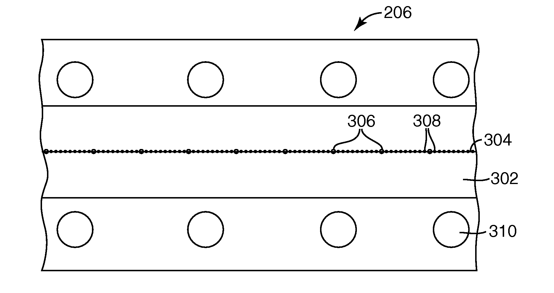
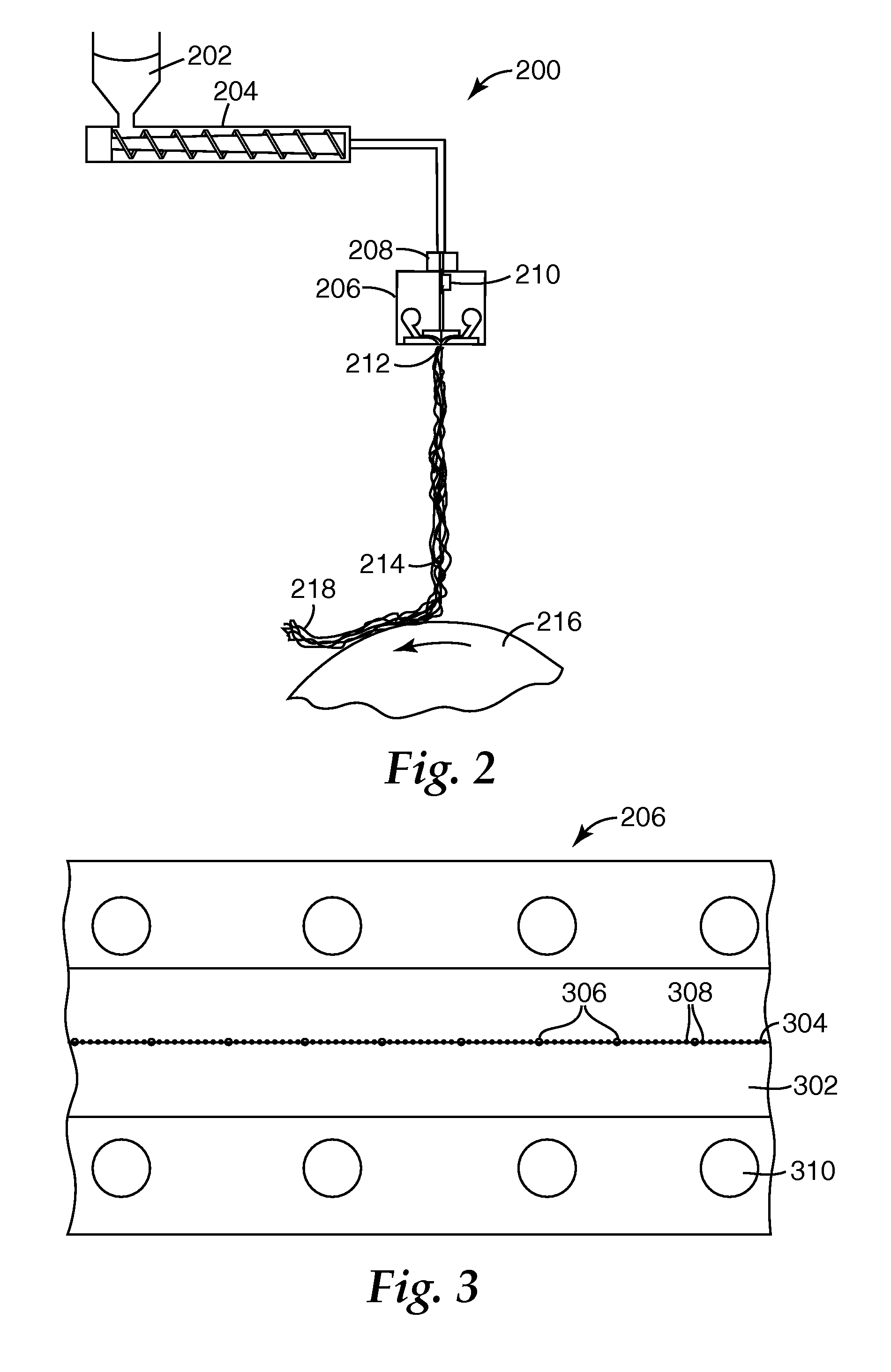
[0066]Using an apparatus like that shown in FIG. 2 and FIG. 3 and procedures like those described in Wente, Van A. “superfine Thermoplastic Fiber”, Industrial and Engineering Chemistry, vol. 48. No. 8, 1956, pp 1342-1346 and Naval Research Laboratory Report 111437, Apr. 15, 1954, four monocomponent monolayer meltblown webs were formed from TOTAL™ 3960 350 melt flow rate polypropylene available from Total Petrochemicals to which had been added 1% tristearyl melamine as an electret charging additive. The polymer was fed to a Model 20 DAVIS STANDARD™ 2 in. (50.8 mm) single screw extruder from the Davis Standard Division of Crompton & Knowles Corp. The extruder had a 20 / 1 length / diameter ratio and a 3 / 1 compression ratio. A Zenith 10 cc / rev melt pump metered the flow of polymer to a 10 in. (25.4 cm) wide drilled orifice meltblowing die whose original 0.012 in. (0.3 mm) orifices had been modified by drilling out every 21st orifice to 0.025 in. (0.6 mm), thereby providing a 20:1 ratio of ...

example 2

[0071]Using the general method of Example 1, webs were made from 100% TOTAL 3960 polypropylene and then 1) corona charged or 2) corona and hydrocharged with distilled water. Set out below in Table 2A are the Run Number, charging technique, basis weight, EFD, web thickness, initial pressure drop, initial NaCl penetration and Quality Factor QF for each web.

[0072]

TABLE 2AQualityBasisPressureFactor,RunChargingWt.,EFD,Thickness,Drop, mmInitial1 / mmNo.TechniquegsmμmmmH2OPenetration, %H2O2-1FCorona23714.23.236.7032.40.172-2FCorona / 23714.23.236.7713.20.30Hydrocharged2-3FCorona19713.32.825.7328.70.222-4FCorona / 19713.32.825.936.30.47Hydrocharged

[0073]The Table 2A webs were next molded using the method of Example 1 to form cup-shaped molded matrices for use as personal respirators. Set out below in Table 2B are the Run Number, King Stiffness, initial pressure drop, and initial NaCl penetration for the molded matrices.

[0074]

TABLE 2BPressureKingDrop, mmInitialRun No.Stiffness, NH2OPenetration, %2...

example 3

[0076]Using the method of Example 1, webs were made from TOTAL 3960 polypropylene to which had been added 0.8% CHIMASSORB 944 hindered amine light stabilizer from Ciba Specialty Chemicals as an electret charging additive and then hydrocharged with distilled water. Set out below in Table 3A are the Run Number, basis weight, EFD, web thickness, initial pressure drop, initial NaCl penetration and Quality Factor QF for each web.

[0077]

TABLE 3AQualityBasisPressureFactor,RunWt.,EFD,Thickness,Drop, mmInitial1 / mmNo.gsmμmmmH2OPenetration, %H2O3-1F24617.92.954.270.8111.133-2F203182.413.372.0901.15

[0078]The Table 3A webs were next molded using the method of Example 1 to form cup-shaped molded matrices for use as personal respirators. Set out below in Table 3B are the Run Number, King Stiffness, initial pressure drop, and initial NaCl penetration for the molded matrices.

[0079]

TABLE 3BPressureKingDrop, mmInitialRun No.Stiffness, NH2OPenetration, %3-1M2.895.300.5913-2M1.963.901.064

[0080]The data i...


PUM

PropertyMeasurementUnit
sizeaaaaaaaaaa
heightaaaaaaaaaa
heightaaaaaaaaaa

Abstract

A porous monocomponent nonwoven web contains a bimodal mass fraction / fiber size mixture of intermingled continuous microfibers and larger size fibers of the same polymeric composition. There are at least five times as many microfibers as larger size fibers, and a histogram of the mass fraction of fibers vs. fiber size exhibits a larger size fiber mode greater than 10 μm. The web may be made by flowing fiber-forming material through a die cavity having larger size orifices and at least five times as many smaller size orifices to form filaments, attenuating the filaments into fibers and collecting the attenuated fibers to form the nonwoven web. The web is especially well suited to the manufacture of self-supporting three dimensional articles such as molded cup-shaped respirators and pleated air filters.

Description

FIELD OF THE INVENTION[0001]This invention relates to meltblown webs and meltblowing equipment.BACKGROUND[0002]Patents or applications relating to nonwoven webs, their manufacture and articles made therefrom include U.S. Pat. No. 3,981,650 (Page), U.S. Pat. No. 4,100,324 (Anderson), U.S. Pat. No. 4,118,531 (Hauser), U.S. Pat. No. 4,536,440 (Berg), U.S. Pat. No. 4,547,420 (Krueger et al.), U.S. Pat. No. 4,931,355 (Radwanski et al.), U.S. Pat. No. 4,988,560 (Meyer et al.), U.S. Pat. No. 5,227,107 (Dickenson et al.), U.S. Pat. No. 5,374,458 (Burgio) U.S. Pat. No. 5,382,400 (Pike et al. '400), U.S. Pat. No. 5,679,042 (Varona), U.S. Pat. No. 5,679,379 (Fabbricante et al.), U.S. Pat. No. 5,695,376 (Datta et al.), U.S. Pat. No. 5,707,468 (Arnold et al.), U.S. Pat. No. 5,721,180 (Pike et al. '180), U.S. Pat. No. 5,817,584 (Singer et al.), U.S. Pat. No. 5,877,098 (Tanaka et al.), U.S. Pat. No. 5,902,540 (Kwok), U.S. Pat. No. 5,904,298 (Kwok et al.), U.S. Pat. No. 5,993,543 (Bodaghi et al.), ...

Claims


Application Information

Patent Timeline
Patent Type & Authority Patents(United States)
IPC IPC(8): D04H1/56D04H3/00D04H3/16
CPCB01D39/1623D01D5/082D04H3/02D01F6/06D04H1/565D01D5/0985B01D2239/064D04H1/56Y10T442/614Y10T442/60Y10T442/68Y10T442/681Y10T442/608Y10T442/619B01D46/52B01D39/00
Inventor BRANDNER, JOHN M.KOPECKY, WILLIAM J.ANGADJIVAND, SEYED A.SPRINGETT, JAMES E.LINDQUIST, TIMOTHY J.
Owner 3M INNOVATIVE PROPERTIES CO
Why Eureka
Try Eureka