Respirator having preloaded nose clip

a nose clip and nose tube technology, applied in the direction of breathing masks, breathing protection, protective garments, etc., can solve the problems of eyeglasses being fogged, eyeglasses entering the wearer's breathing track, and it is difficult to achieve a snug fit over the nose portion of the wearer, so as to improve the fit and/or comfort. effect of nos

Inactive Publication Date: 2012-05-08
3M INNOVATIVE PROPERTIES CO
View PDF50 Cites 75 Cited by
  • Summary
  • Abstract
  • Description
  • Claims
  • Application Information

AI Technical Summary

Benefits of technology

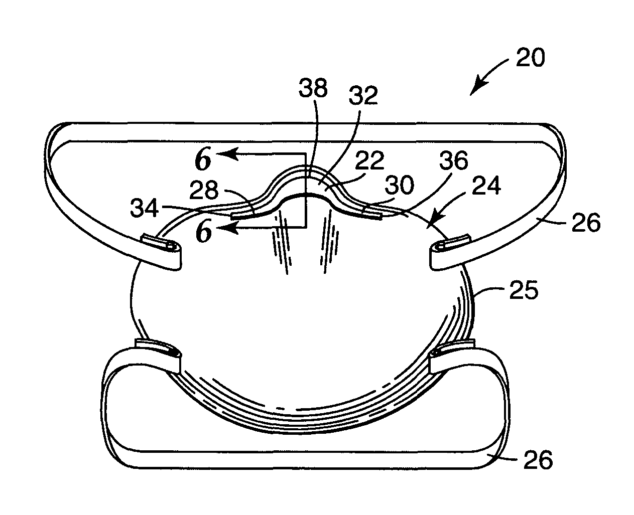
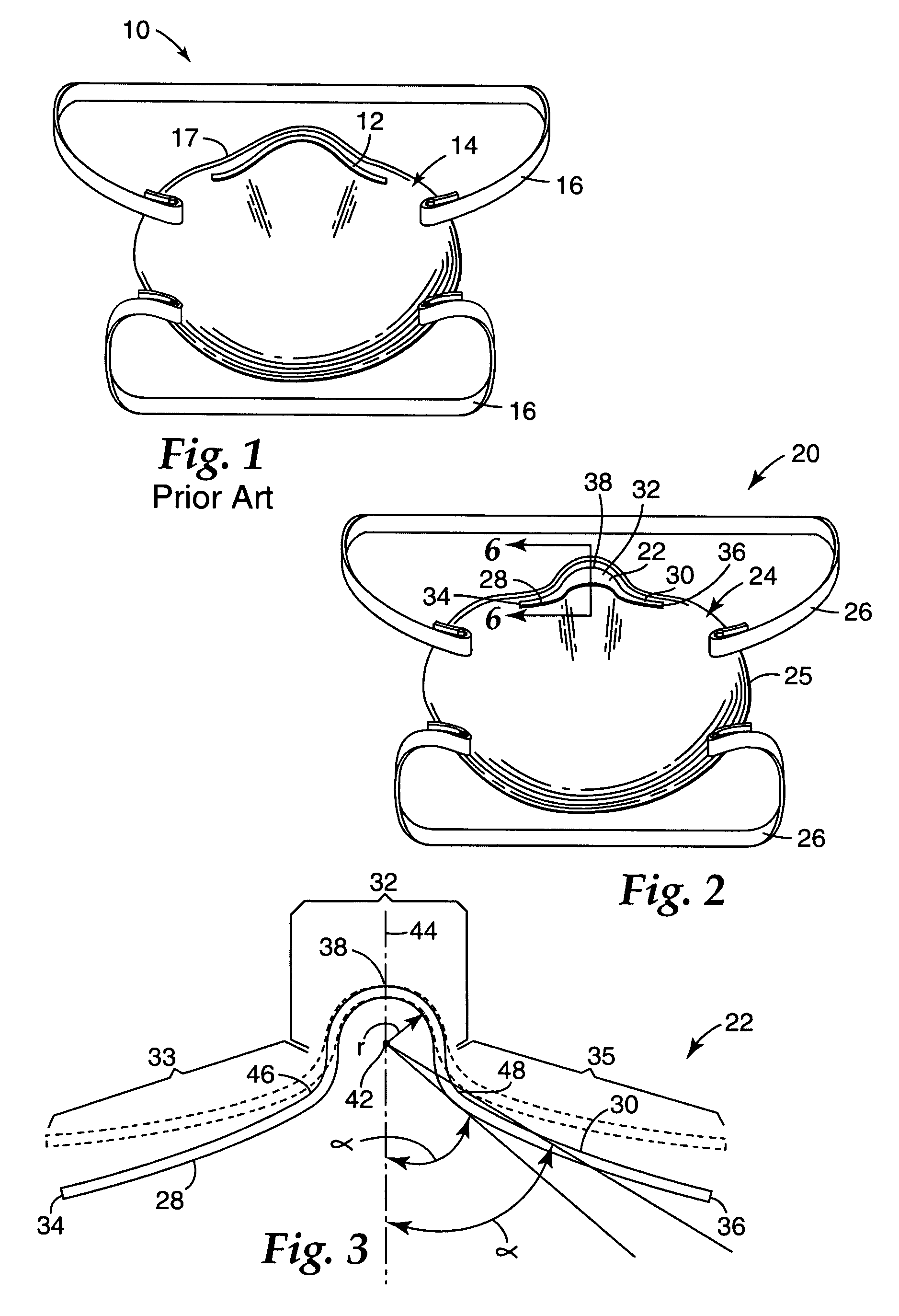
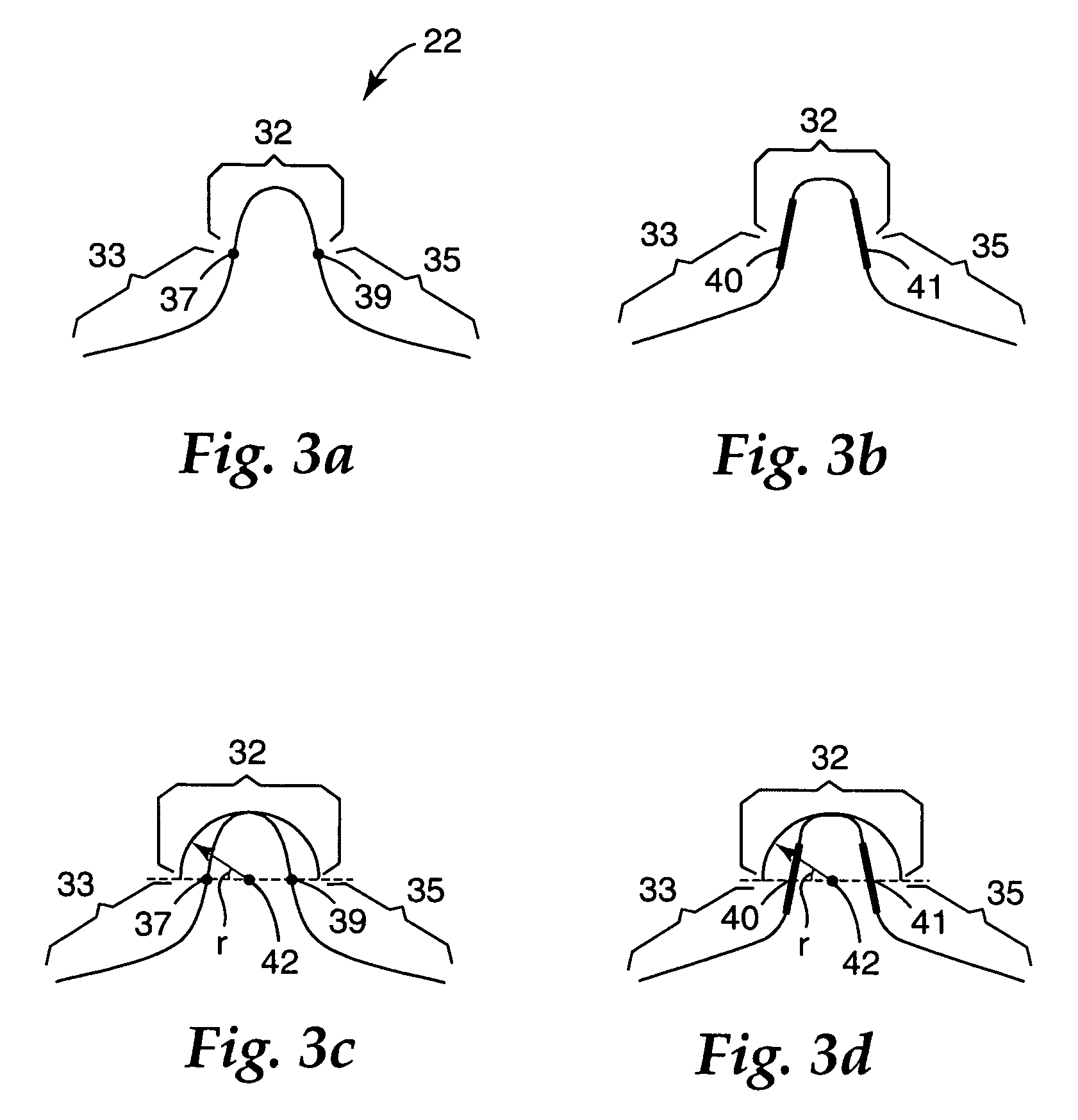
[0007]Unlike known respirators, the inventive respirator does not require that its nose clip be individually shaped by each user to achieve a proper fit. Because the nose clip has a predefined shape that enables a force to be exerted on each side of the wearer's nose when the mask is worn, the user does not have to adapt the shape of the nose clip to achieve a good seal. Further, the predefined shape, and the force that is exerted inward on each side of the nose by the first and second wing portions, precludes the nose clip from changing from an intended shape, and therefore the clip does not require any need for readapting its shape to prevent leakage. The present invention thus requires less effort and maintenance by the wearer to achieve a good fit. Another benefit of the invention is that the nose clip can be readily made from known plastic materials, which can be easily incinerated with the mask body when the respirator has met the end of its service life.
[0024]“nose foam” means a compressible porous material that is adapted for placement on the interior of a mask body to improve the fit and / or comfort over the nose;

Problems solved by technology

In the nose region, however, there is a radical change in contour, which makes it difficult to achieve a snug fit over that portion of the wearer's face.
Failure to obtain a snug fit allows air to enter or exit the respirator interior without passing through the filter media.
In this situation, contaminants may enter the wearer's breathing track, and other persons or things may be exposed to contaminants exhaled by the wearer.
In addition, a wearer's eyeglasses can become fogged when the exhalate escapes from the respirator interior over the nose region of the mask.
Fogged eyewear, of course, makes visibility more troublesome to the wearer and creates unsafe conditions for the user and others.

Method used


Image

  • Respirator having preloaded nose clip
  • Respirator having preloaded nose clip
  • Respirator having preloaded nose clip

Examples


example 1

[0072]A nose clip of the invention was formed as outlined in the Nose Clip Making Procedure section set forth above. A preform having the configuration of FIG. 7 was cut from a polyethylene terephthalate (PET) film. The preform was attached to a 3M 8210™ respirator mask body (without the standard metal nose clip) using pressure sensitive tape, Scotch 300LSE High Strength, available from the 3M Company, St. Paul, Minn. The tape was applied to the entire underside of the preform to secure it to the mask. After the preform was attached to the mask, it was molded to its predefined shape while mounted to the mask body. The shaping tool shown in FIG. 9 was used to shape the preform into a nose clip. The preform was molded at a temperature of approximately 88° C. while applying a clamp force of approximately 10 Newtons for about 5 to 6 seconds. While formed on the tool, the nose clip was cooled to a temperature of approximately 60° C. for 5 to 6 minutes. Twenty masks were created in this m...

example 2

[0073]A nose clip of the invention was formed as outlined in the Nose Clip Making Procedure section set forth above. A preform that had the shape of FIG. 7, was cut from a PET film. The preform was attached to a 3M 8511™ respiratory mask body using ultrasonic welding. The preform was welded to the mask at points extending from the ends 34 and 36, inward along the β dimension, as shown in FIG. 7. After the preform was attached to the mask, it was molded to its predefined shape using the molding tool 74 shown in FIG. 9. Molding was carried out at a temperature of approximately 88° C. using a clamp force of about 10 Newtons for 5 to 6 seconds. While in the tool, the nose clip was cooled to a temperature of approximately 60° C. for 5 to 6 minutes. TIL was evaluated on three masks made in this fashion. The resulting TIL was 1.6%, 0.2%, and 6.6% on three masks fitted to three individuals.

example 3

[0074]A nose clip of the invention was formed as outlined in the Nose Clip Making Procedure section set forth above. A perform having the configuration shown in FIG. 10 was cut from PET film. The preform was attached to a 3M 8511™ respiratory mask body (without the standard metal nose clip) using ultrasonic welding. The preform was welded to the mask at points extending from the ends 34 and 36, inward along the Σ dimension, as shown in FIG. 8. After the preform was attached to the mask, it was molded on the mask using the molding tool 76 of FIG. 10 at a temperature of approximately 93° C., a clamp force of about 10 Newtons, and a dwell time of 3 to 4 seconds. While in the tool, the nose clip was cooled to a temperature of approximately 60° C. for 5 to 6 minutes. The mask of this example had good face fitting characteristics.


PUM


Abstract

A respirator that includes a mask body and a nose clip. The mask body is adapted to fit over the nose and mouth of a person, and the nose clip is placed on the mask body to extend over the bridge of the wearer's nose when the mask is worn. The nose clip has a predefined shape that comprises first and second wings. These wings exert a force resiliently inward on each side of the wearer's nose when the mask is worn. The invention eliminates the need for the wearer to individually shape the nose clip to the wearer's nose.

Description

[0001]The present invention pertains to a respiratory mask that has a nose clip that is located on a mask body such that it exerts a compression force on opposing sides of the wearer's nose when the mask is worn. The force occurs as a result of the predefined shape that is provided to the nose clip.BACKGROUND[0002]Respirators (sometimes referred to as “filtering face masks” or “filtering face pieces”) are worn over the breathing passages of a person for two common purposes: (1) to prevent impurities or contaminants from entering the wearer's breathing track; and (2) to protect other persons or things from being exposed to pathogens and other contaminants exhaled by the wearer. In the first situation, the respirator is worn in an environment where the air contains particles that are harmful to the wearer, for example, in an auto body shop. In the second situation, the respirator is worn in an environment where there is risk of contamination to others persons or things, for example, i...

Claims


Application Information

Patent Timeline
Patent Type & Authority Patents(United States)
IPC IPC(8): A62B17/00A62B18/02
CPCA62B23/025A41D13/1146A62B23/02
Inventor XUE, THOMAS J.GEBREWOLD, YONAS
Owner 3M INNOVATIVE PROPERTIES CO
Why Eureka
Try Eureka