Drilling and producing deep water subsea wells

a technology for producing deep water subsea wells and drilling vessels, which is applied in the direction of quarries, well accessories, waste water treatment, etc., can solve the problems of time-consuming, inability to readily test the check valve of the tubing annulus, and the inability to have such a completion riser available in the drilling vessel. achieve the effect of optimal efficiency within the separation system

Inactive Publication Date: 2005-11-29
VETCO GRAY
View PDF37 Cites 73 Cited by
  • Summary
  • Abstract
  • Description
  • Claims
  • Application Information

AI Technical Summary

Benefits of technology

[0010]In another aspect of the invention, the tree is connected to a flowline leading to a subsea fluid separator. The outlet of the subsea fluid separator leads to a choke to control the flowrate. The choke leads to a subsea manifold. This arrangement is important in minimizing flow disturbance prior to entering the separator, and supports optimum efficiency within the separation system.

Problems solved by technology

While workable, it is time consuming, however to assemble and run a dual string completion riser.
Also, drilling vessels may not have such a completion riser available, requiring one to be supplied on a rental basis.
A disadvantage is that one cannot readily test a tubing annulus check valve to determine whether or not it is properly closing.
However, these typically require hydraulic passages in the tubing hanger, which take up space and add complexity to the tubing hanger, rendering the designs potentially unreliable due to space restrictions.
However, in some instances, a platform might drill and case a number of nearby wells, and defer running the production trees until later.
Generally, however, trees are run either on a completion riser or on drill pipe because they are large and very heavy.
Being unable to run a production tree from a platform at the same time that the platform is drilling or completing another slows field development.

Method used


Image

  • Drilling and producing deep water subsea wells
  • Drilling and producing deep water subsea wells
  • Drilling and producing deep water subsea wells

Examples


Embodiment Construction

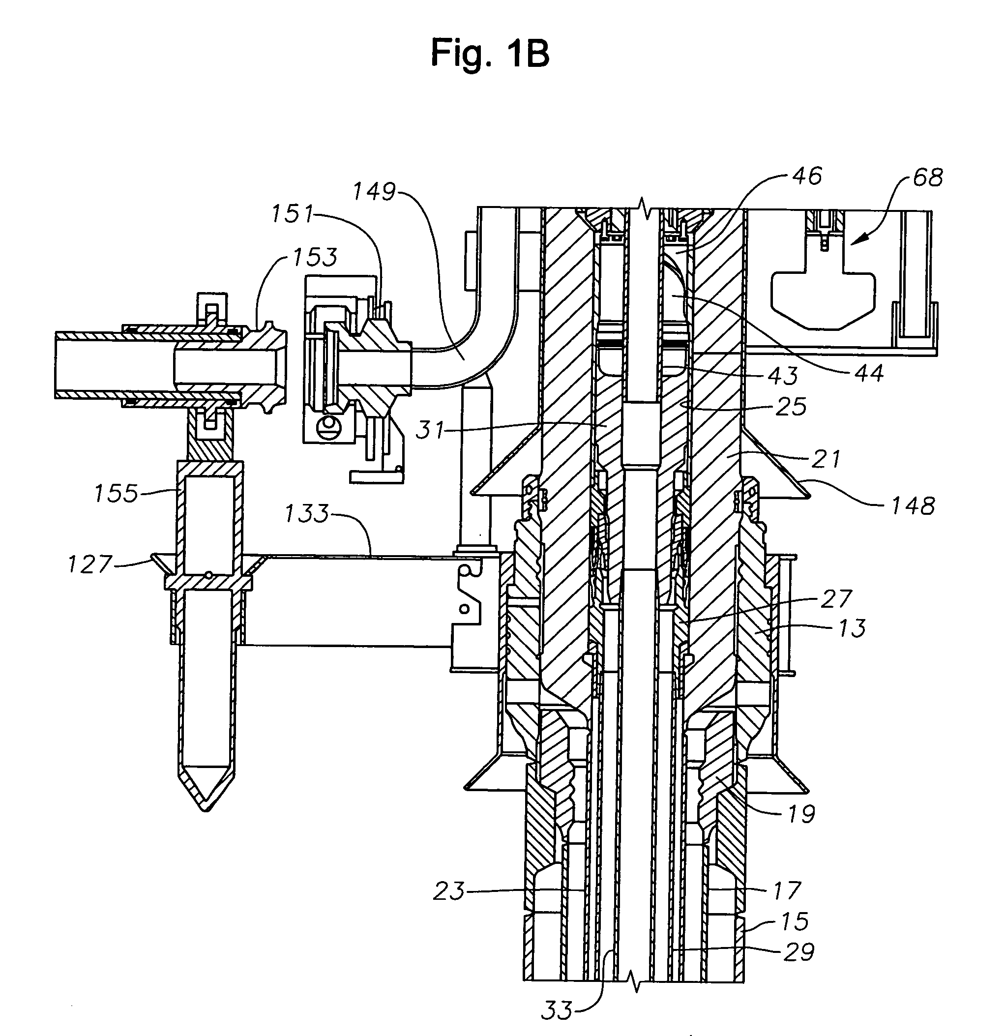
[0044]Overall Structure of Subsea Wellhead Assembly

[0045]Referring to FIG. 1B, a lower portion of a wellhead assembly 11 includes an outer or low pressure wellhead housing 13 that locates on the sea floor and is secured to a string of large diameter conductor pipe 15 that extends into the well. In this embodiment, a first string of casing 17 is suspended on a lower end of outer wellhead housing 13 by a hanger 19. However, casing 17 and hanger 19 are not always suspended from the outer wellhead housing 13 and can be eliminated in many cases.

[0046]An inner or high pressure wellhead housing 21 lands in and is supported within the bore of outer wellhead housing 13. Inner wellhead housing 21 is located at the upper end of a string of casing 23 that extends through casing 17 to a greater depth. Inner wellhead housing 21 has a bore 25 with at least one casing hanger 27 located therein. Casing hanger 27 is sealed within bore 25 and secured to the upper end of a string of casing 29 that exte...


PUM

PropertyMeasurementUnit
distancesaaaaaaaaaa
thicknessaaaaaaaaaa
diameteraaaaaaaaaa

Abstract

Subsea wells are drilled and completed with an offshore floating platform in a manner that allows simultaneous work on more than one well. A first well is drilled and cased. Then a tubing hanger is run through a drilling riser and landed in the wellhead housing. Then, with the same floating platform, the drilling riser is disconnected and moved to a second well. While performing operations on the second well, the operator lowers a production tree from the floating platform on a lift line, and connects it to the first wellhead housing. An ROV assisted subsea plug removal tool is used for plug removal and setting operations. Seabed separation is configured upstream of a production choke valve.

Description

CROSS-REFERENCE TO RELATED APPLICATION[0001]This application claims priority to provisional application 60 / 425,377, filed Nov. 12, 2002.BACKGROUND OF THE INVENTION[0002]A typical subsea wellhead assembly has a high pressure wellhead housing supported in a lower pressure wellhead housing and secured to casing that extends into the well. One or more casing hangers land in the wellhead housing, the casing hanger being located at the upper end of a string of casing that extends into the well to a deeper depth. A string of tubing extends through the casing for conveying production fluids. A Christmas or production tree mounts to the upper end of the wellhead housing for controlling the well fluid. The production tree is typically a large, heavy assembly, having a number of valves and controls mounted thereon.[0003]One type of tree, sometimes called “conventional” or “vertical”, has two bores through it, one of which is the production bore and the other is the tubing annulus access bore. ...

Claims


Application Information

Patent Timeline
Patent Type & Authority Patents(United States)
IPC IPC(8): B01D17/00B01D17/02C02F1/40C02F1/48E21B33/038E21B43/36E21B43/40
CPCB01D17/0211B01D17/00E21B43/40E21B43/36E21B33/038C02F1/48B01D17/0208B01D17/0217B01D17/045B01D17/06B01D17/0214C02F2101/32C02F2103/10C02F2103/06C02F1/40B01D17/12E21B29/12E21B29/08E21B34/04E21B34/045E21B23/00E21B33/064E21B33/076E21B43/017
Inventor FENTON, STEPHEN P.LANGFORD, GAWAINDEZEN, FRANCISCOSOLLIE, LARS-PETTERMICHAELSEN, JARLESOELVIK, NILS ARNE
Owner VETCO GRAY
Why Eureka
Try Eureka