
Pneumatic tire

a pneumatic tire and tire body technology, applied in the field of pneumatic tires, can solve the problems of pneumatic tire abnormal wear, rubber does not flow satisfactorily, and the tire is not easily inflated and inflated

Inactive Publication Date: 2007-03-22
YOKOHAMA RUBBER CO LTD
View PDF17 Cites 56 Cited by
  • Summary
  • Abstract
  • Description
  • Claims
  • Application Information

AI Technical Summary

Benefits of technology

[0008] It is an object of the present invention to at least partially solve the problems in the conventional technology.

Problems solved by technology

When manufacturing pneumatic tires having protrusions in the grooves, however, the protrusions become obstacle to flow of rubber for forming the tread area inward in the tire radial direction of the protrusion.
If the breaker ply is deformed in this manner, abnormal wear may occur to the pneumatic tire due to the deformation in the breaker ply when a vehicle to which the pneumatic tires are fit travels.
However, if the protrusion is too large, then the rubber does not satisfactorily flow into a mold for forming the protrusion, and it is difficult to discharge the air present between the mold and the rubber during manufacture of the pneumatic tire.
As a result, the pneumatic tire is manufactured without obtaining a targeted shape of the protrusion, which causes failure in manufacture, i.e., occurrence of “bare” (depressed area).

Method used


Image

  • Pneumatic tire
  • Pneumatic tire
  • Pneumatic tire

Examples


Embodiment Construction

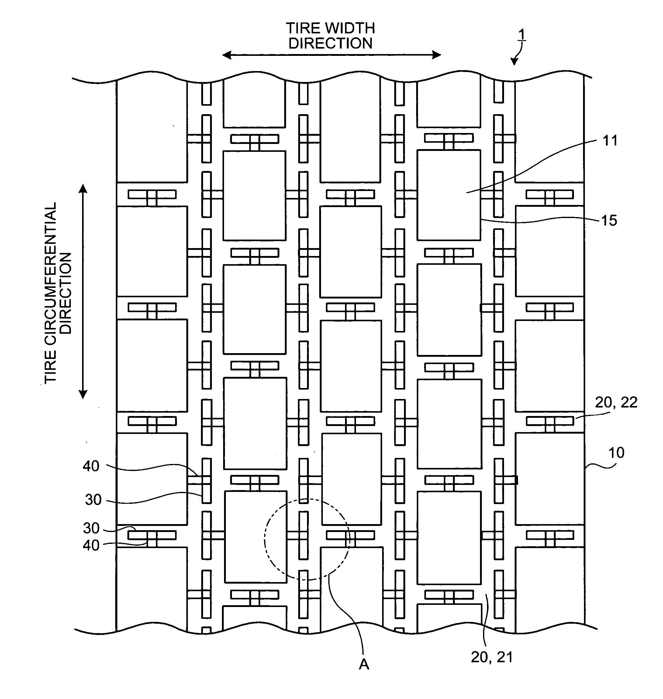
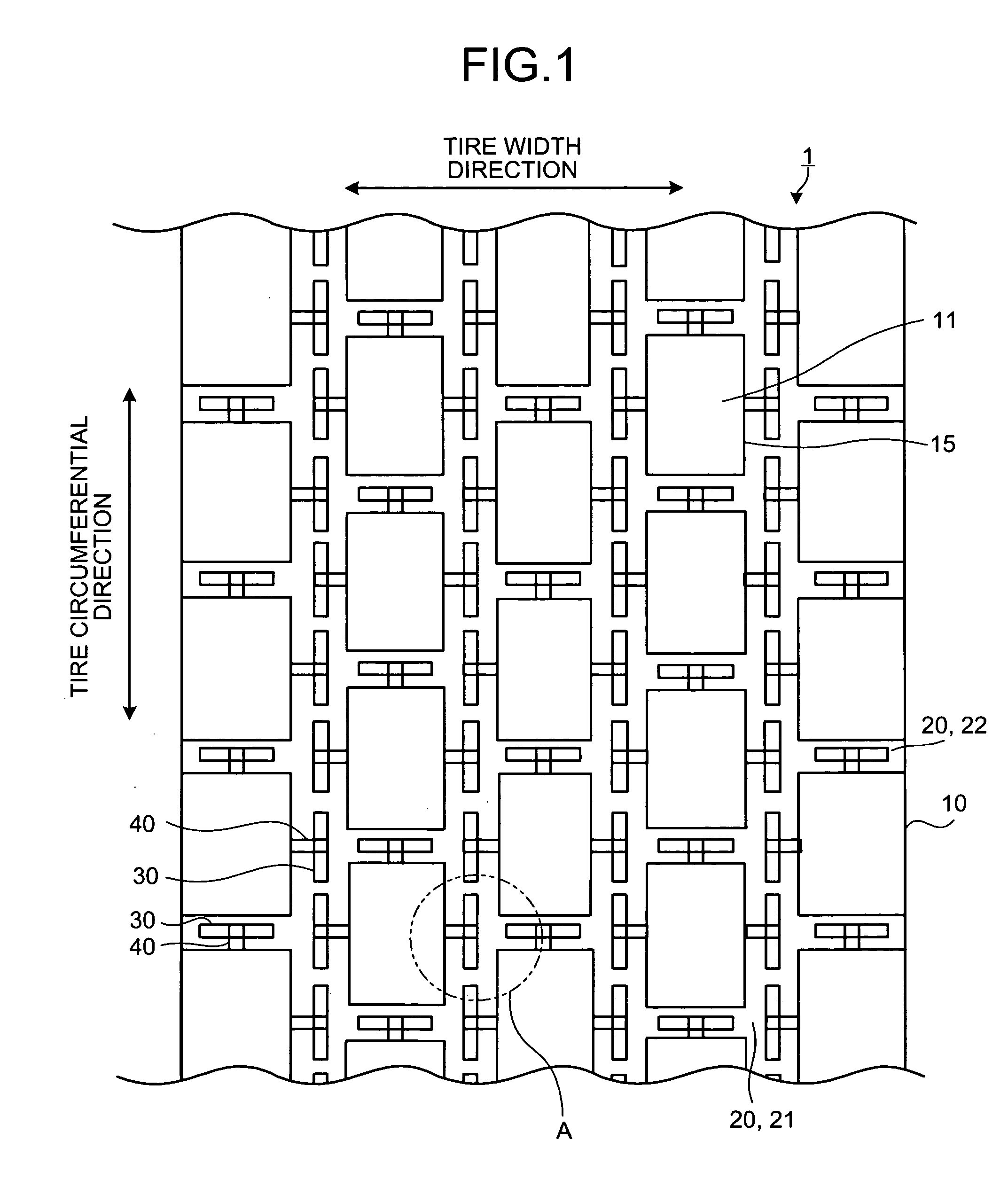
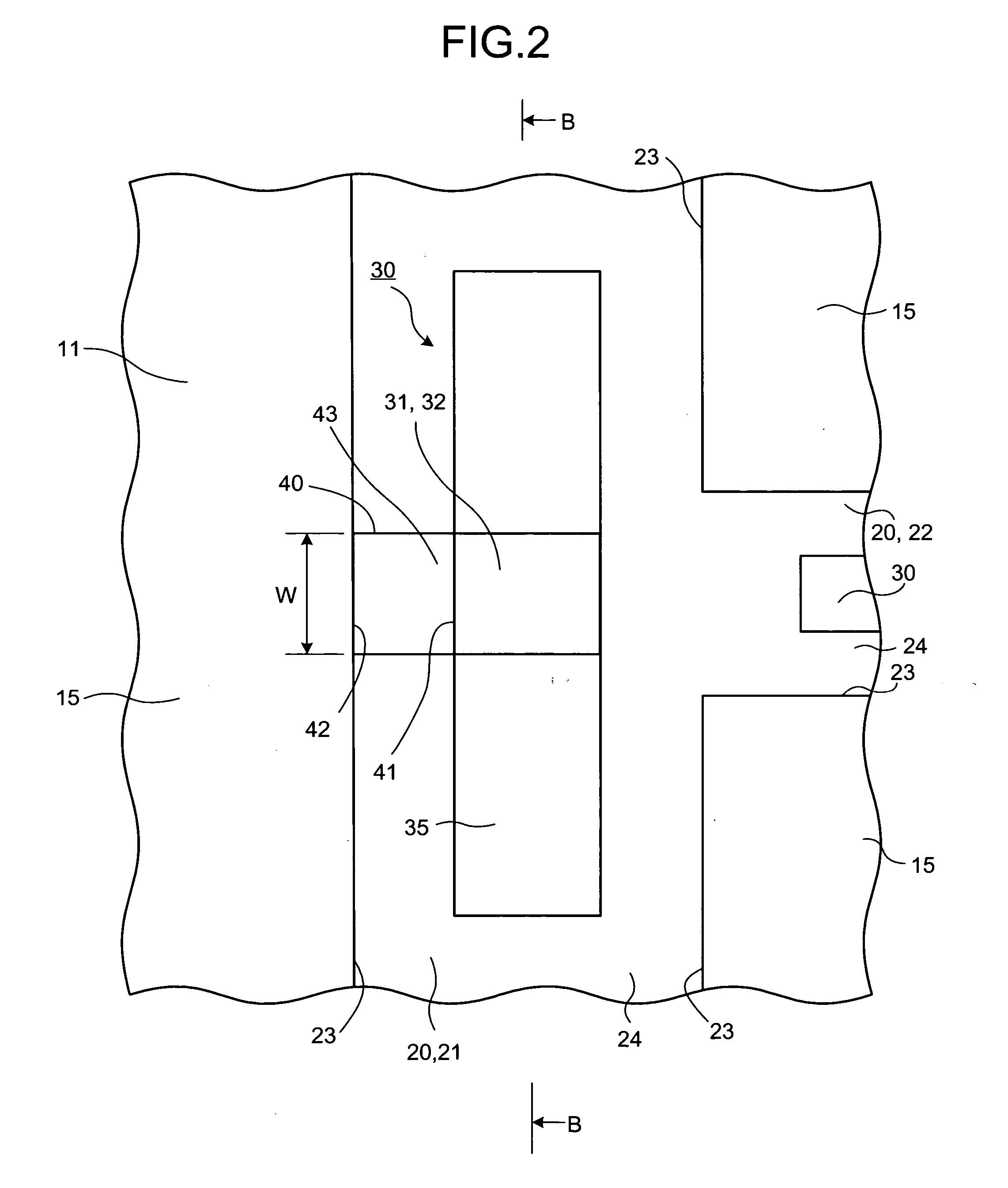
[0023] Exemplary embodiments of the present invention are explained in detail below with reference to the accompanying drawings. It is to be noted that the present invention is not limited by the embodiments. Constituent elements explained in the following embodiments include those easily replaceable therewith by persons skilled in the art, or those substantially equivalent thereto. Types of pneumatic tires include a block type tread, a ribbed tread, and a ribbed-lug tread. In the following embodiments, the pneumatic tire having the block type tread will be explained as an example of the pneumatic tire.

[0024] In the embodiments, a tire width direction means a direction parallel to a rotating axis of the pneumatic tire, an inward in the tire width direction means a direction toward an equatorial plane in the tire width direction, and an outward in the tire width direction means a direction opposite to the direction toward the equatorial plane in the tire width direction. Moreover, a...


PUM


Abstract

A pneumatic tire includes a plurality of protrusions on a bottom of each of the grooves. The height of the protrusion is variable in a profile of the protrusion in a circumference direction of the pneumatic. The protrusion has at least one peak portion that protrudes away from a center of the pneumatic tire. The pneumatic tire further includes a connection member between the protrusion and an adjacent one of the lands, the connection member having a first end toward the land and a second end toward the peak portion, a height of the first end from the bottom of the groove being larger than that of the second end.

Description

BACKGROUND OF THE INVENTION [0001] 1. Field of the Invention [0002] The present invention generally relates to a pneumatic tire. The present invention specifically relates to a pneumatic tire capable of suppressing stone trapping. [0003] 2. Description of the Related Art [0004] Stones are sometimes trapped within grooves that are formed on the tread area of pneumatic tires of vehicles. When the stones are trapped within the grooves, so-called “stone drilling” may occur. The stone drilling is a phenomenon that stones penetrate the bottoms of the grooves due to rolling of the pneumatic tire to cause damage to the tread area. To take care of this issue, some of the conventional pneumatic tires have protrusions in the grooves to minimize stone trapping in the grooves. Due to the provision of the protrusions, even if stones enter the grooves, the stones are ejected to the outside of the grooves by the elastic force of the protrusion. [0005] When manufacturing pneumatic tires having protr...

Claims


Application Information

Patent Timeline
Patent Type & Authority Applications(United States)
IPC IPC(8): B60C11/13
CPCB60C11/13Y10S152/01Y10S152/902B60C11/047
Inventor OYAMA, TOSHIRO
Owner YOKOHAMA RUBBER CO LTD
Features
  • Generate Ideas
  • Intellectual Property
  • Life Sciences
  • Materials
  • Tech Scout
  • Unparalleled Data Quality
  • Higher Quality Content
  • 60% Fewer Hallucinations
Learn More