Device and procedure for the pneumatic atomization of liquids through an implosive gas flow

a technology of implosive gas flow and device, which is applied in the direction of medical atomisers, liquid spraying apparatus, fire rescue, etc., can solve the problems of poor operation, low productivity, and low efficiency of electrospray

Inactive Publication Date: 2007-03-22
UNIV DE SEVILLA OTRI - UNIV DE SEVILLA
View PDF17 Cites 33 Cited by
  • Summary
  • Abstract
  • Description
  • Claims
  • Application Information

AI Technical Summary

Benefits of technology

[0001] The object of the current invention is a device and a procedure for the atomization or nebulization of a liquid by using an impulsion gas or steam (hereinafter, gas) pressurized into such device. Both fluids are expelled to the outside after their mixture, causing the liquid to exit as a spray or suspension of droplets that is carried by the gas flow. The device consists of a liquid chamber, contained in a vessel or pressurized bottle, and a liquid-gas mixing zone, where the combination between both phases and their exit occurs. The impulsion gas gets into the bottle through an injection inlet, subsequently leaving such vessel through the mixing zone. The free surface of the liquid within the bottle is pressurized by the impulsion gas, causing the liquid to be impelled to the mixing zone through a feeding tube whose nozzle is close to the bottom of the bottle. At the other end of the feeding tube, called nebulizer end, there is an exit hole. Said exit section is approximately opposed to a vessel exit orifice, through which the mixed liquid/gas goes out to the outside as a suspen...

Problems solved by technology

As a result, operation is poor when the liquid causes abrasion of the nozzle or when there is sedimentation altering the ejection geometry.
The impelling gas can be CFCs (Chlorofluorocarbon), with the subsequent environmental uncertainty.
However, for applications where a sufficiently large liquid flow rate is to...

Method used


Image

  • Device and procedure for the pneumatic atomization of liquids through an implosive gas flow
  • Device and procedure for the pneumatic atomization of liquids through an implosive gas flow
  • Device and procedure for the pneumatic atomization of liquids through an implosive gas flow

Examples


example of embodiment

OF THE INVENTION

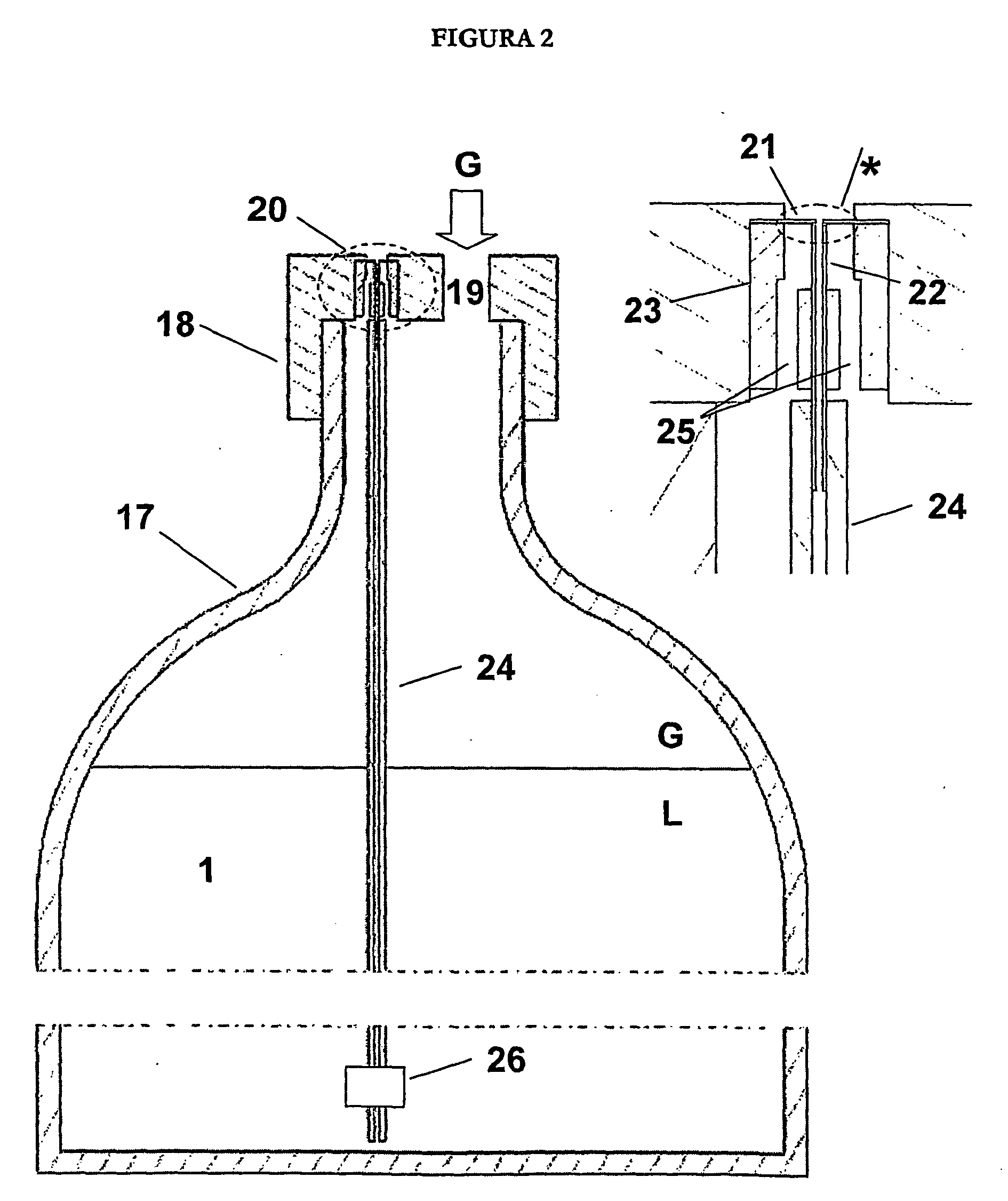
[0054] Next the embodiment of a real device is shown where the AFF technology has been successfully integrated (see FIG. 2). Said device is made of a two litre capacity plastic bottle (17), in whose opening there is a threaded lid (18), made out of plastic as well. The screw must be leakproof, by means of a sealant or a suitable o-ring. The gas coming from an external pressurization source is introduced through an opening (19) in the lid. In the present execution such pressurization source is an air diaphragm pump consuming 15 watts of power.

[0055] Also, there is a cavity (20, see detail) in the lid, where several parts are integrated: [0056] (a) a steel disc (21) of 4 millimetres diameter and 0,1 millimetres thickness with an orifice of 0,4 performed in its centre. [0057] (b) A capillary tubing (22) of steel with an inner diameter of 0,4 millimetres with a straight profile on its tip and placed 0,1 millimetres from the inner plate face (21), [0058] (c) A plastic po...


PUM


Abstract

The invention relates to a device and method for the atomisation or nebulisation of a liquid using a propellant vapour or gas (referred to hereafter as gas) which is introduced into the device under pressure. According to the invention, the two fluids are mixed together and subsequently released to the exterior, such that the liquid is released in the form of an aerosol or a suspension of drops that is conveyed by the gas stream. The inventive device comprises a liquid storage chamber which is housed in a pressurised cylinder or container and a liquid/gas mixing area whereat the aforementioned two phases are combined and released to the exterior.

Description

SUMMARY [0001] The object of the current invention is a device and a procedure for the atomization or nebulization of a liquid by using an impulsion gas or steam (hereinafter, gas) pressurized into such device. Both fluids are expelled to the outside after their mixture, causing the liquid to exit as a spray or suspension of droplets that is carried by the gas flow. The device consists of a liquid chamber, contained in a vessel or pressurized bottle, and a liquid-gas mixing zone, where the combination between both phases and their exit occurs. The impulsion gas gets into the bottle through an injection inlet, subsequently leaving such vessel through the mixing zone. The free surface of the liquid within the bottle is pressurized by the impulsion gas, causing the liquid to be impelled to the mixing zone through a feeding tube whose nozzle is close to the bottom of the bottle. At the other end of the feeding tube, called nebulizer end, there is an exit hole. Said exit section is appro...

Claims


Application Information

Patent Timeline
IPC IPC(8): A62C13/62
CPCA61M11/02A62C13/64B05B7/0458B05B7/2437B05B7/1686B05B7/2416B05B7/2427B05B7/1626A61M11/002A61M11/065B05D7/00
Inventor GANAN CALVO, ALFONSO MIGUELMENDOZA SIMON, ELADIORIESCO CHUECA, PASCUAL
Owner UNIV DE SEVILLA OTRI - UNIV DE SEVILLA
Why Eureka
Try Eureka