
Delivery of video mail and video mail receipt notifications

Inactive Publication Date: 2007-03-22
GLENAYRE ELECTRONICS INC
View PDF6 Cites 64 Cited by
  • Summary
  • Abstract
  • Description
  • Claims
  • Application Information

AI Technical Summary

Benefits of technology

[0008] The present invention addresses the above-described needs in the art by providing techniques for the delivery of video messages, such as video mail, by delivering

Problems solved by technology

In the fast paced, always connected world that we live in today, such treatment is certainly not accepted.
However, with the introduction of such technology, users are faced with yet another message depository that much be periodically checked to determine if a message is waiting.
Furthermore, the burden associated with this task can be even more exaggerated by the fact that special user devices may be required to access and playback video messages.

Method used


Image

  • Delivery of video mail and video mail receipt notifications
  • Delivery of video mail and video mail receipt notifications
  • Delivery of video mail and video mail receipt notifications

Examples


Embodiment Construction

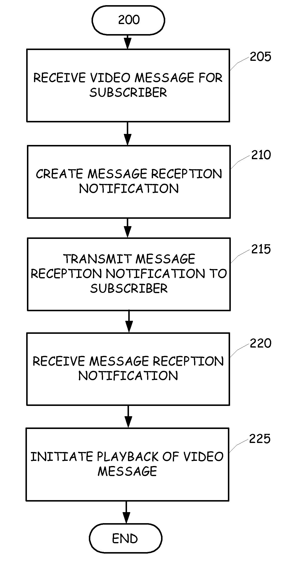
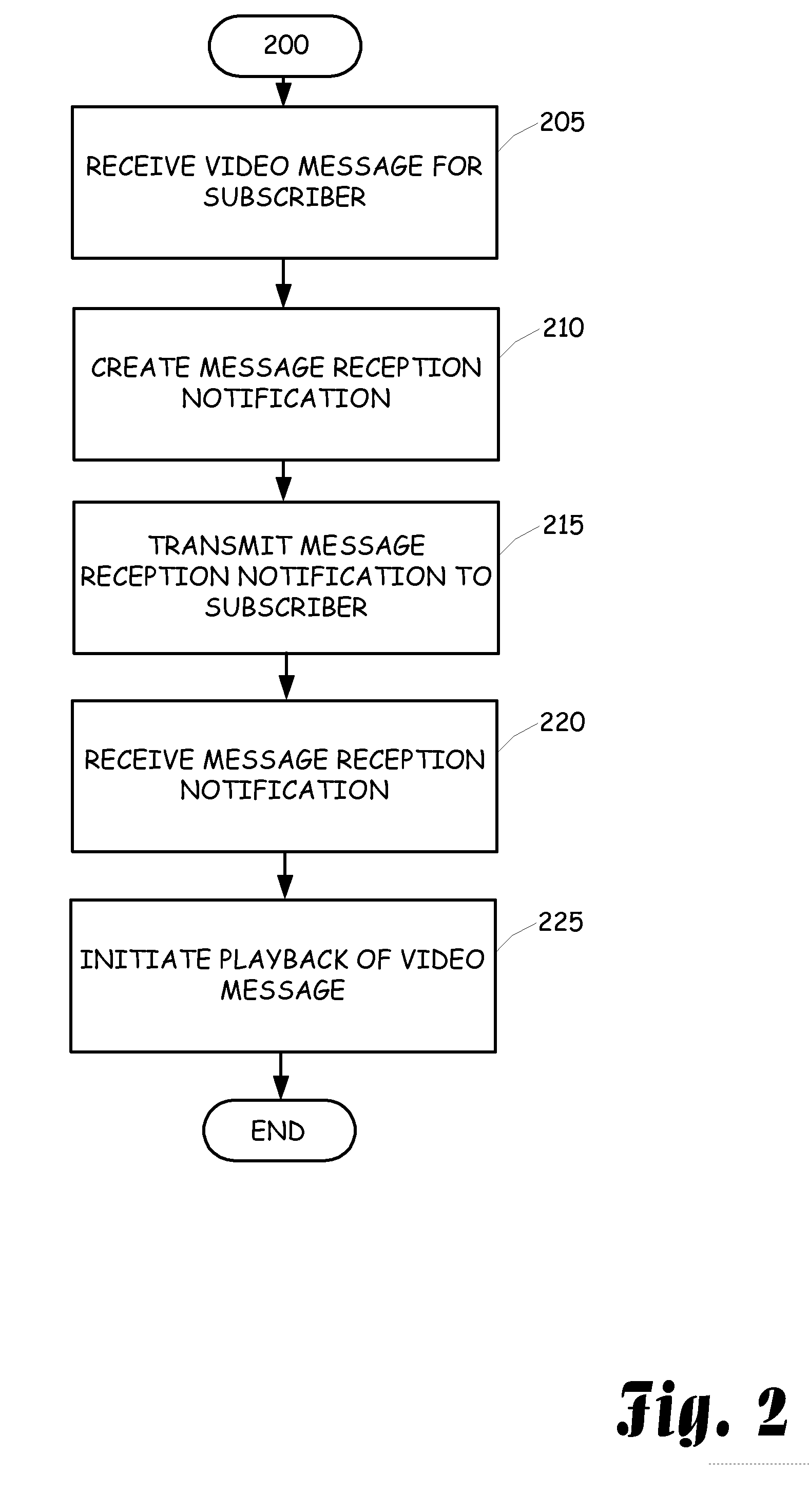
[0019] The present invention is directed towards enhancing the deliver of video messages to a subscriber by either providing alternate mechanisms for the delivery of the video message or by facilitating access to the video message for a subscriber.

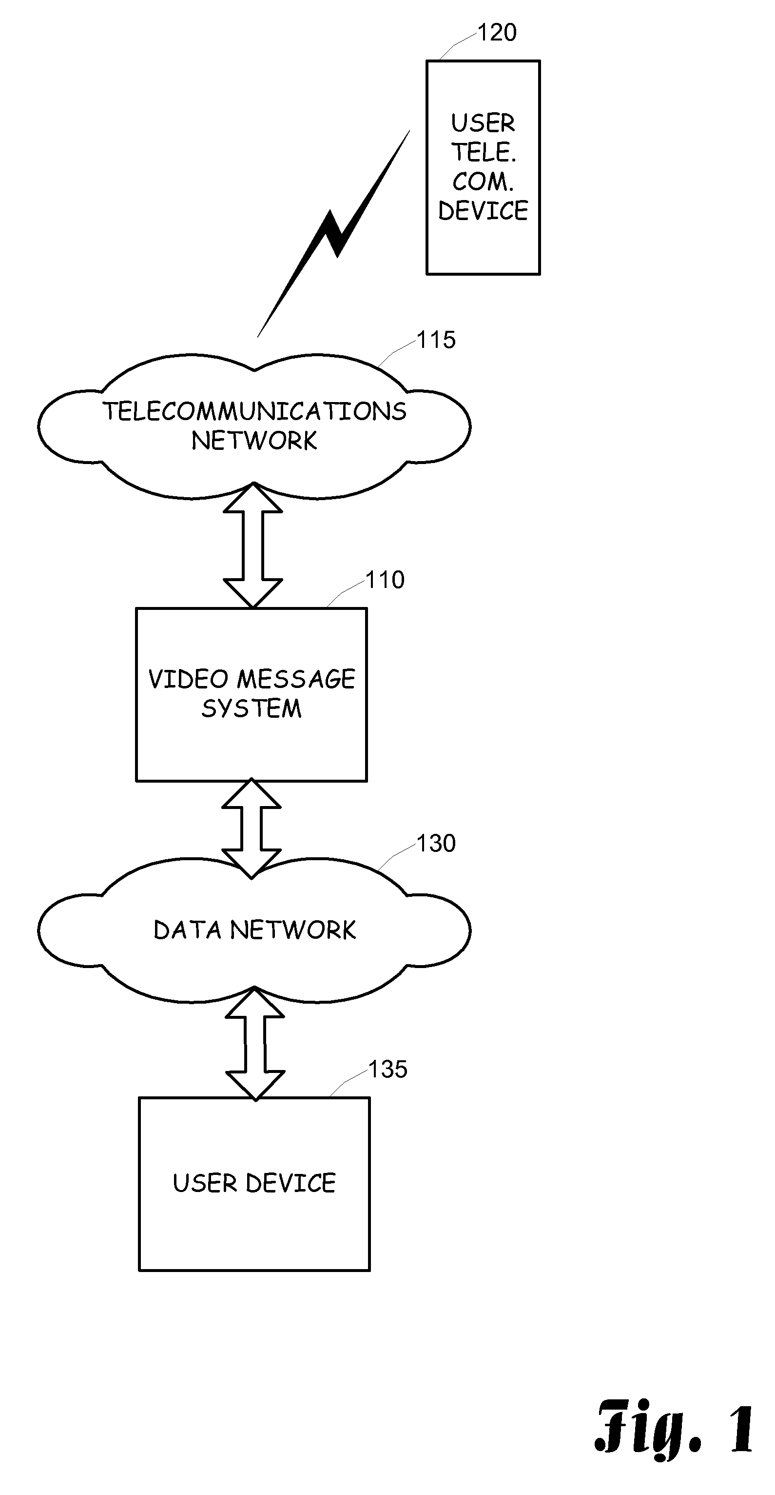
[0020]FIG. 1 is a block diagram illustrating an exemplary environment in which various embodiments of the present invention can be implemented. The illustrated environment includes a video messaging system 110 that is communicatively coupled to a telecommunications network 115 and a data network 130. The video messaging system 110 communicates with one or more user telecommunication devices 120 through the telecommunications network 115. In addition, the video messaging system communicates with one or more user devices 135 through the data network 130.

[0021] The video messaging system 110 can exist in a variety of configurations. One such configuration is the video messaging telecommunications platform described in the above-referenced r...


PUM


Abstract

Video content is delivered in a bandwidth efficient manner to a destination device. The video content is analyzed and a compression operation is performed on the video content prior to delivery to the destination device. Any audio associated with the video content is maintained in synchronization with the video content. The compression of the video can be performed in a variety of manners including single transmission of static frames, combining substantially similar frames so that only a single frame representing the combination is transmitted, and only transmitting dynamically changing or active portions of the video content.

Description

CROSS-REFERENCE TO RELATED APPLICATIONS [0001] This application is a continuation-in-part of United States patent application filed on Mar. 15, 2005 and assigned Ser. No. 11 / 080,744, United States patent application filed on Jun. 29, 2005 and assigned Ser. No. 11 / 170,459, and United States patent application filed on Jun. 29, 2005 and assigned Ser. No. 11 / 170,530, each of which claim the benefit of the filing date of United States Provisional Application for patent entitled DISTRIBUTED IP ARCHITECTURE FOR TELECOMMUNICATIONS SYSTEM, filed on Jun. 30, 2004 and assigned Ser. No. 60 / 584,117. [0002] This application is related to a United States patent application Ser. No. ______ that has a title of DISTRIBUTED IP ARCHITECTURE FOR TELECOMMUNICATIONS SYSTEM WITH VIDEO MAIL, was filed concurrently with this application and is hereby incorporated by reference in its entirety.BACKGROUND OF THE INVENTION [0003] The present invention relates to the techniques for the delivery of video mail or ...

Claims


Application Information

Patent Timeline
IPC IPC(8): G06F15/16
CPCH04M1/72555G06Q10/107H04M1/72439
Inventor BETTIS, SONNY R.MORAES, IAN M.PLOTKY, JON S.LOWMAN, PHILIP L.SPENCER, JAMES H.
Owner GLENAYRE ELECTRONICS INC
Learn More