Plasma display apparatus

a technology of display apparatus and plasma, which is applied in the direction of instruments, static indicating devices, etc., can solve the problems of electrical damage to the data driver integrated circuit, and achieve the effects of preventing excessive current displacement, preventing electrical damage to the data driver integrated circuit, and preventing undesired discharg

Inactive Publication Date: 2007-03-29
LG ELECTRONICS INC
View PDF2 Cites 9 Cited by
  • Summary
  • Abstract
  • Description
  • Claims
  • Application Information

AI Technical Summary

Benefits of technology

[0023] Further, to accomplish the above object, a plasma display apparatus of the present invention comprises a plasma display panel on which a plurality of scan electrodes and a plurality of data electrodes intersecting the plurality of scan electrodes are formed, a scan driver of causing the scan order of the plurality of scan electrodes different from a first data pattern in a second data pattern to be different from the first data pattern among the data patterns of inputted image data to scan the scan electrode, and causing the width of scan pulse supplied to a first scan electrode among the plurality of scan electrodes upon scanning the scan electrode to be different from the width of scan pulse supplied to a second scan electrode having a different scan order from ...

Problems solved by technology

There is a problem in that electrical damage to the data driver integrated circuit occurs because the displacement current over...

Method used


Image

  • Plasma display apparatus
  • Plasma display apparatus
  • Plasma display apparatus

Examples


Embodiment Construction

[0063] Preferred embodiments of the present invention will be described in a more detailed manner with reference to the drawings.

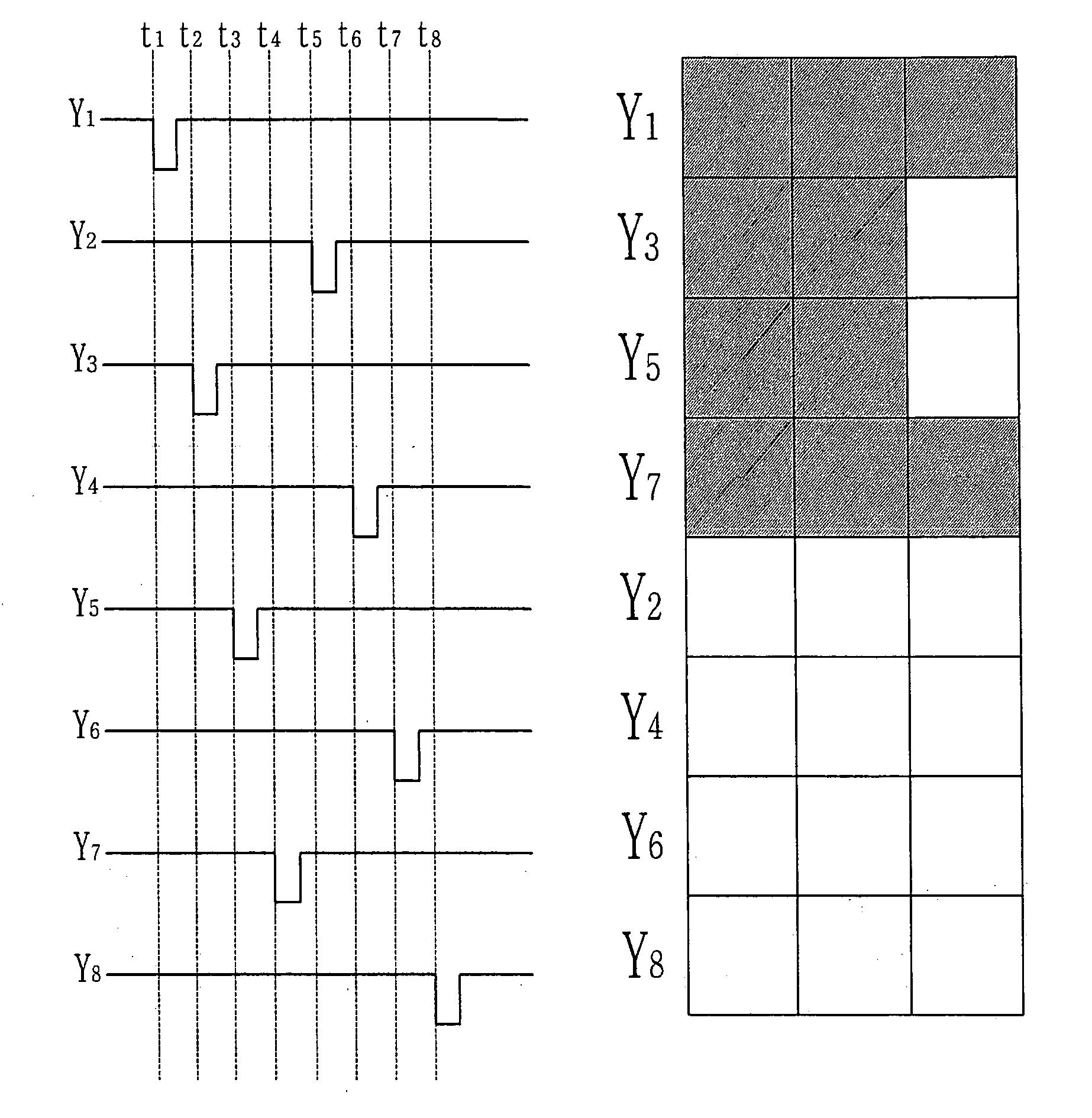
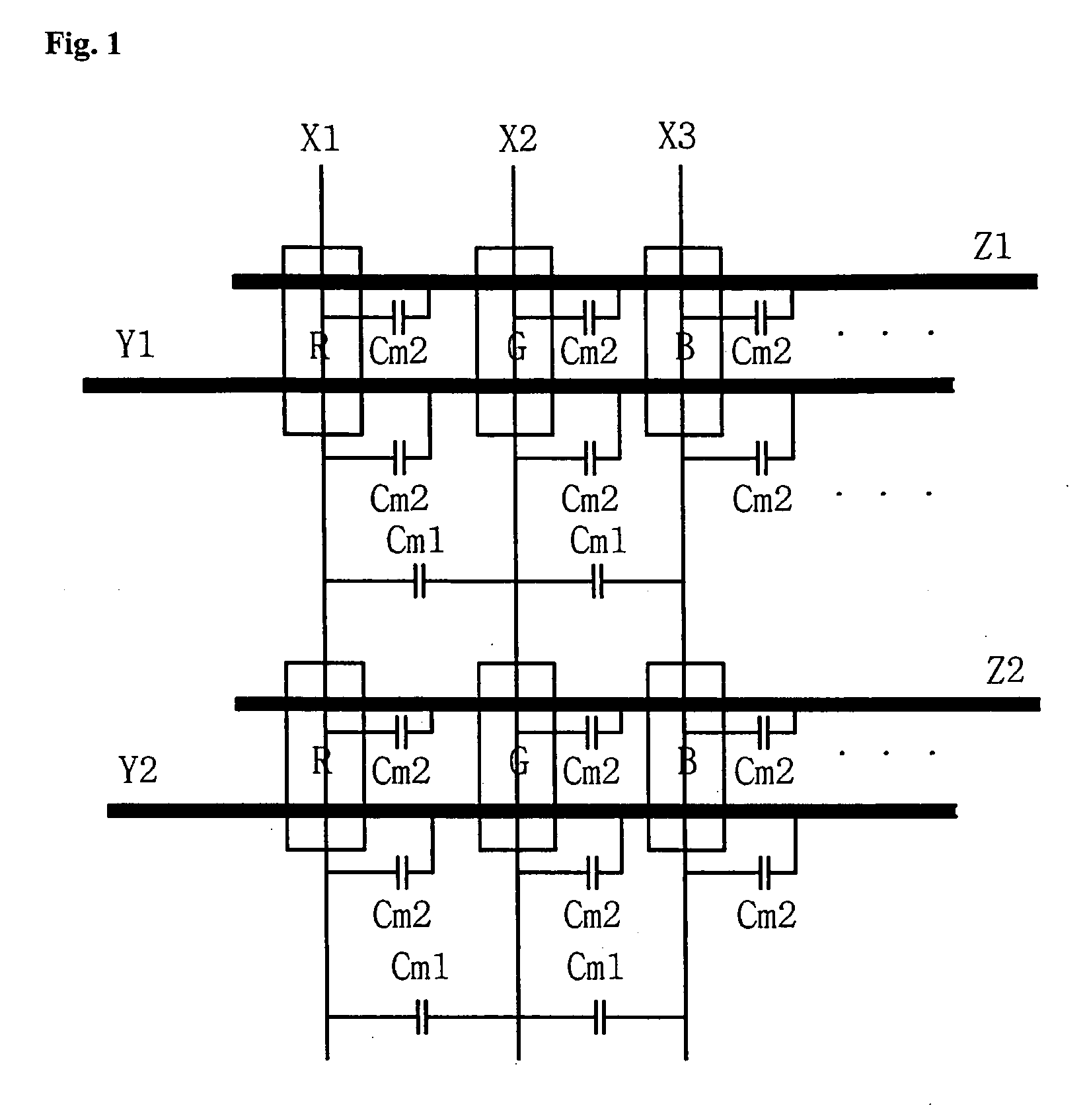
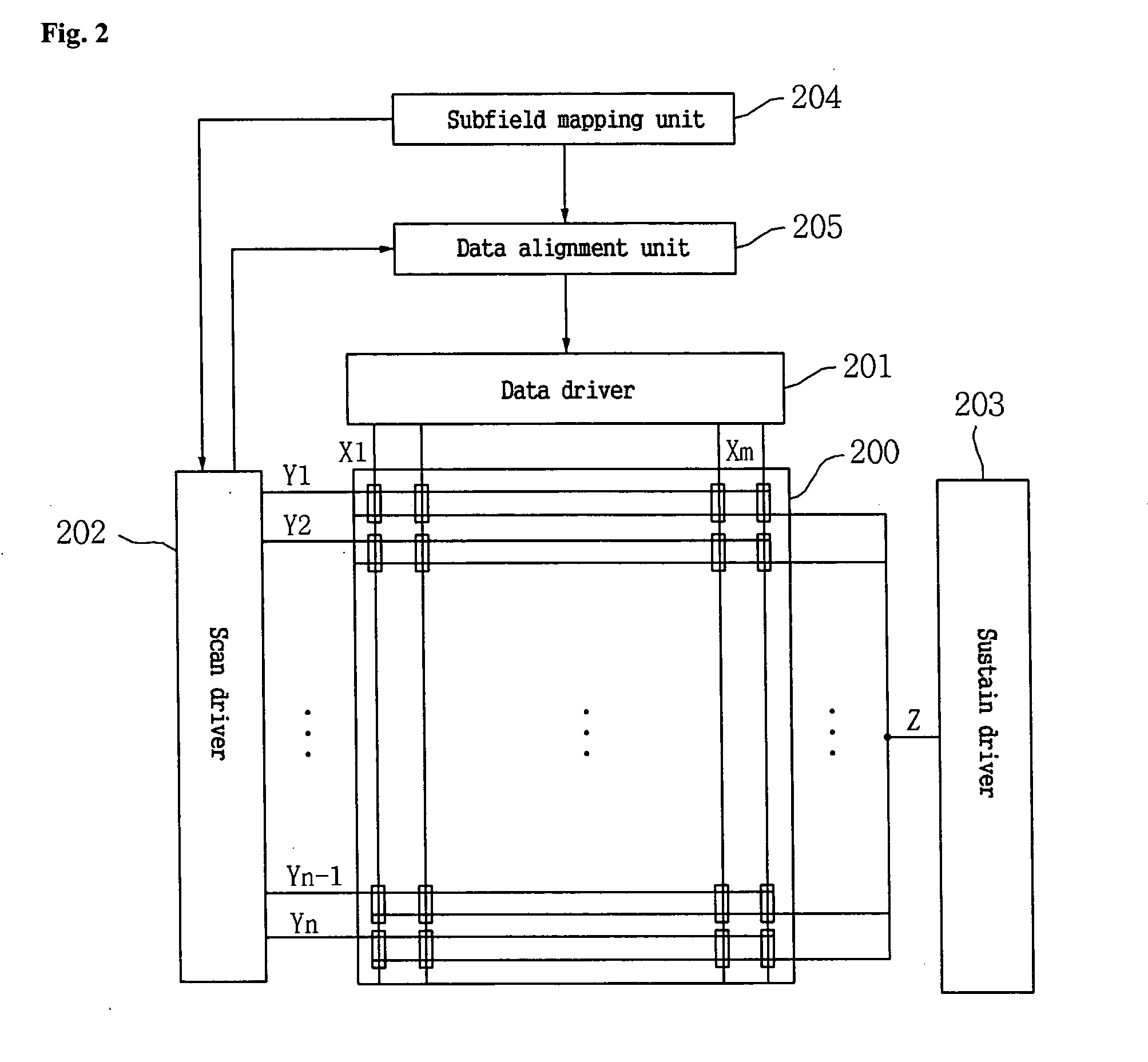
[0064] To accomplish the above objects, a plasma display apparatus comprises a plurality of scan electrodes, a plurality of data electrodes intersecting the plurality of scan electrodes, a scan driver for scanning the scan electrode with one scan type among a plurality of scan types in which an order of scanning the plurality of scan electrodes is different from each other in an address period, and causing the width of a scan pulse supplied to a first scan electrode among the plurality of scan electrodes upon scanning the scan electrode to be different from the width of a scan pulse supplied to a second scan electrode having a different scan order from the first scan electrode, and a data driver of supplying a data pulse to the data electrode corresponding to the one scan type.

[0065] The scan driver calculates the displacement current corresponding to ea...


PUM


Abstract

The present invention relates to a plasma display apparatus of scanning a scan electrode Y with one or more scan types among a plurality of scan types. The present invention has an effect of preventing the excessive displacement current from beign generated by scanning the scan electrodes with any one of a plurality of scan types, and thus preventing electrical damage to the data driver integrated circuit. The present invention is preferred to include a plurality of scan electrodes, a plurality of data electrodes intersecting the plurality of scan electrodes, a scan driver for scanning the scan electrode with one scan type among a plurality of scan types in which an order of scanning the plurality of scan electrodes is different from each other in an address period, and causing the width of scan pulse supplied to a first scan electrode among the plurality of scan electrodes upon scanning the scan electrode to be different from the width of scan pulse supplied to a second scan electrode having a different scan order from the first scan electrode, and a data driver of supplying a data pulse to the data electrode corresponding to the one scan type.

Description

CROSS-REFERENCES TO RELATED APPLICATIONS [0001] This Nonprovisional application claims priority under 35 U.S.C. § 119(a) on Patent Application No. 10-2005-0089004 filed in Korea on Sep. 23, 2005, the entire contents of which are hereby incorporated by reference. BACKGROUND OF THE INVENTION [0002] 1. Field of the Invention [0003] The present invention relates to a plasma display apparatus, and more particularly, to a plasma display apparatus of scanning a scan electrode Y with one or more scan types among a plurality of scan types. [0004] 2. Background of the Related Art [0005] In a conventional plasma display panel, barrier ribs formed between a front panel and a rear panel of the panel constitute a cell, and an inert gas containing a main discharge gas such as Ne, He, or mixture gas of Ne+He and small amount of Xe is injected into each cell. This plurality of cells constitutes a pixel. For example, a red, a green, and a blue cells constitute a pixel. [0006] In the plasma display pa...

Claims


Application Information

Patent Timeline
IPC IPC(8): G09G3/28G09G3/288G09G3/293
CPCG09G3/293G09G2310/0213G09G2310/0218G09G2330/025G09G2320/041G09G2330/021G09G2310/0227G09G3/296
Inventor PARK, KIRACKBAE, JONGWOONRYU, SEONGHWANCHO, YOONJOOHWANG, DOOYONG
Owner LG ELECTRONICS INC
Why Eureka
Try Eureka