Substrate transfer apparatus

Inactive Publication Date: 2007-03-29
SHINKO ELECTRIC IND CO LTD
View PDF4 Cites 5 Cited by
  • Summary
  • Abstract
  • Description
  • Claims
  • Application Information

AI Technical Summary

Benefits of technology

[0016] Accordingly, bearing in mind the heretofore described problems, the invention has been conceived with an object of providing a substrate transfer apparatus which can accurately transfer a substrate in a condition in which a pattern forming region is widened.
[0025] According to the invention, a position of the substrate is regulated by the substrate position regulating member which makes contact with a side surface of the substrate which is parallel to the transfer direction, on either of the first and second rotary shafts. Thus, it enables the first and second roller to be provided closer to the side surface of the substrate than in the above-described case. By this means, it is possible to accurately transfer the substrate while ensuring the width of a pattern forming region on which a product is manufactured as large.
[0026] According to the invention, it is possible to accurately transfer the substrate while ensuring large width of the pattern forming region.

Problems solved by technology

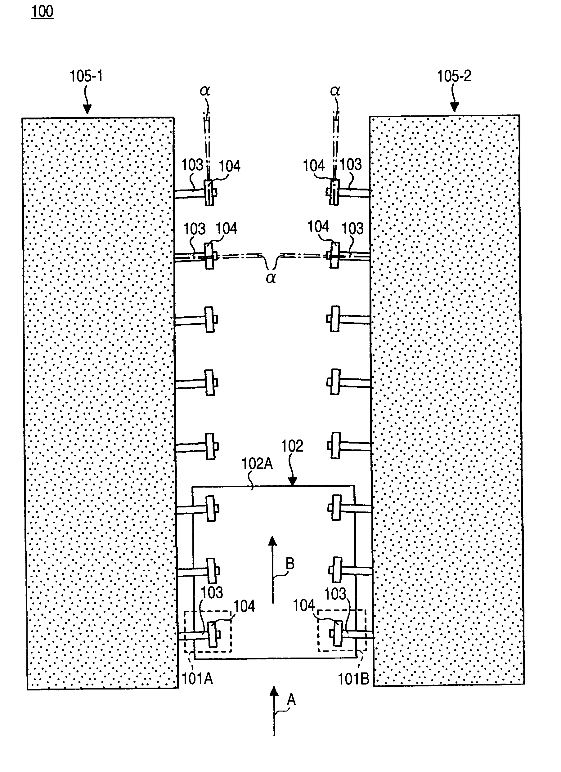
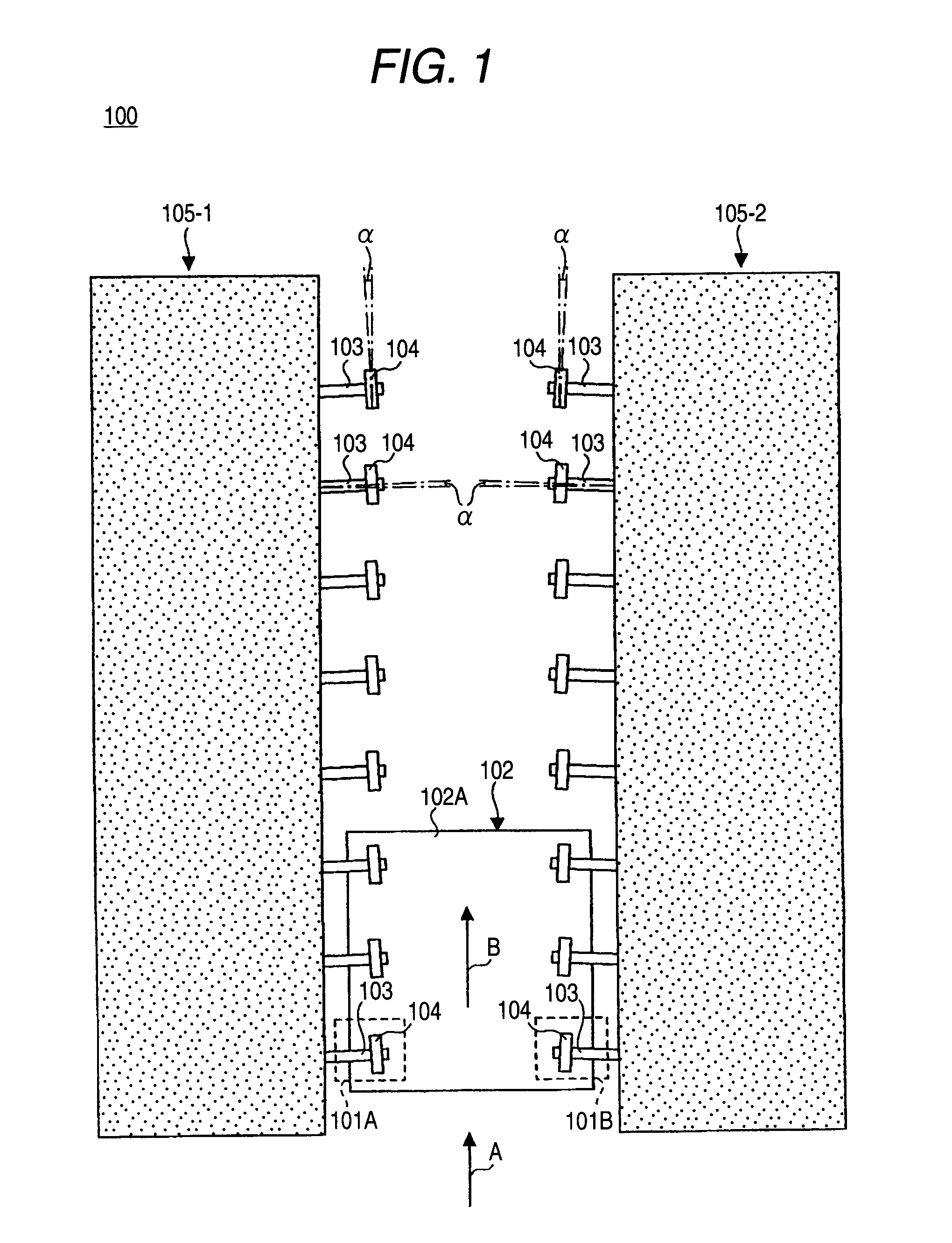
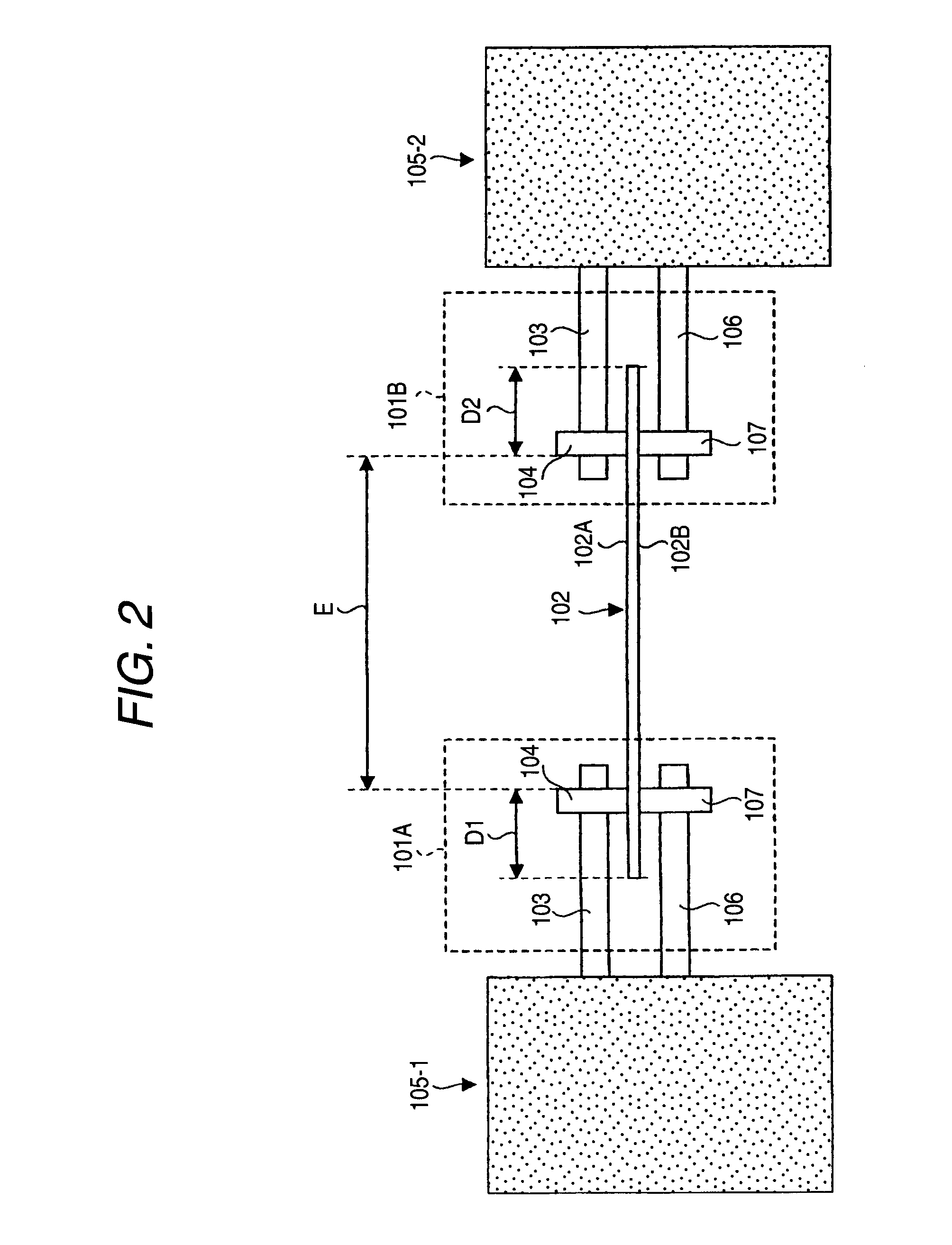
Therefore, there is a problem in that this reduces an area of the pattern forming regions E in which a product is manufactured.
However, in the event that ceramics or metal is used as the material of the upper roller 104 and the lower roller 107, there is a problem in that damage occurs on a surface of the substrate 102 which contacts with the upper roller 104 and the lower roller 107.

Method used


Image

  • Substrate transfer apparatus
  • Substrate transfer apparatus
  • Substrate transfer apparatus

Examples


Embodiment Construction

[0037] Next, an embodiment of the invention will be described with reference to the drawings.

[0038]FIG. 3 is a plan view of a substrate transfer apparatus according to the embodiment of the invention. FIG. 4 is a sectional view of the substrate transfer apparatus shown in FIG. 3. In FIG. 3, G depicts a transfer direction of a substrate 32 (hereafter referred to as a “transfer direction G”), K-1 an axial direction of a second rotary shaft 27-1 (hereafter referred to as an “axial direction K-1), and K-2 an axial direction of a second rotary shaft 27-2 (hereafter referred to as an “axial direction K-2”). Also, in FIG. 3, N depicts a center of the substrate 32 (hereafter referred to as a “center N”), M1 a rotation direction of a second roller 29-1 (hereafter referred to as a “rotation direction M1”), and M2 a rotation direction of a second roller 29-2 (hereafter referred to as a “rotation direction M2”).

[0039] Referring to FIGS. 3 and 4, the substrate transfer apparatus 10 has a first...


PUM


Abstract

A substrate transfer apparatus has pluralities of pairs of substrate support mechanisms. The substrate support mechanism includes a first roller provided on a first rotary shaft and a second roller provided on a second rotary shaft, the substrate support mechanism transfers a substrate in a transfer direction while supporting the substrate between the first and second rollers in a thickness direction of the substrate. The pair of the substrate support mechanisms are disposed so as to oppose to each other in a width direction of the substrate and the pairs of the substrate support mechanisms are arranged along with the transfer direction. Further, a substrate position regulating member that regulates a position of the substrate by contacting with a side surface which is parallel to the transfer direction is provided on either of the first and second rotary shafts.

Description

TECHNICAL FIELD [0001] The present invention relates to a substrate transfer apparatus, and particularly to a substrate transfer apparatus which transfers a variety of substrates, such as a semiconductor wafer, a glass substrate and printed circuit board, while supporting both surfaces of the substrates. BACKGROUND ART [0002] In a case where a product is manufactured by forming a pattern on a front surface or each surface of a substrate such as a semiconductor wafer, a glass substrate or a printed circuit board, a substrate transfer apparatus transferring the substrate is employed. The substrate transfer apparatus is used in, for example, a plating process, an etching process, a cleaning process or the like. [0003] Also, some substrate transfer apparatuses transfer a substrate while supporting both surfaces of the substrate. Such a substrate transfer apparatus is applied to a cleaning apparatus, which sprays the substrate with a process liquid ejected from a spray nozzle, an etching...

Claims


Application Information

Patent Timeline
IPC IPC(8): G03B27/58
CPCH01L21/67051H01L21/6776H01L21/67706H01L21/6708
Inventor SUYAMA, TOSHIAKIKAWAHARA, MAKOTOYAMAZAKI, MASARUROKUGAWA, TAKAHIRO
Owner SHINKO ELECTRIC IND CO LTD
Why Eureka
Try Eureka