Zoom lens system

a technology of zoom lens and zoom lens, applied in the field of zoom lens system, can solve the problems of becoming difficult to achieve the effect of compact, lightweight, and slimming

Inactive Publication Date: 2007-03-29
NIKON CORP
View PDF8 Cites 21 Cited by
  • Summary
  • Abstract
  • Description
  • Claims
  • Application Information

AI Technical Summary

Benefits of technology

[0008] The present invention is made in view of the aforementioned problems and has an object to provide a zoom lens system excellently correcting various aberrations with accomplishing to be compact, lightweight, and slim upon being retracted.

Problems solved by technology

However, a zoom lens system disclosed in Japanese Patent Application Laid-Open No. 2003-287677 has relatively large number of lens elements of eight, so that it becomes difficult to accomplish to be compact, lightweight, and slim when the zoom lens system is accommodated in the camera body.

Method used


Image

  • Zoom lens system
  • Zoom lens system
  • Zoom lens system

Examples


example 1

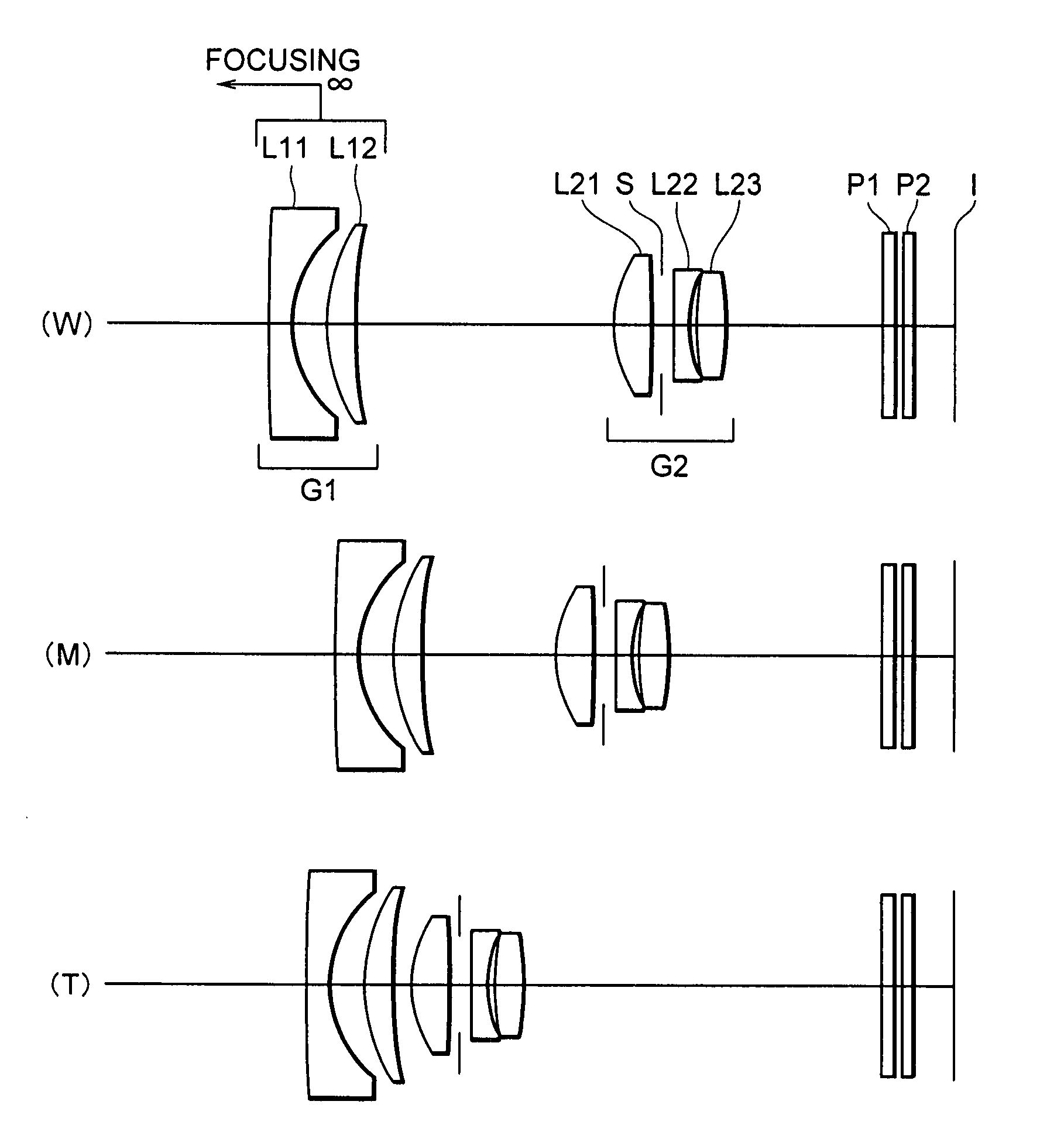
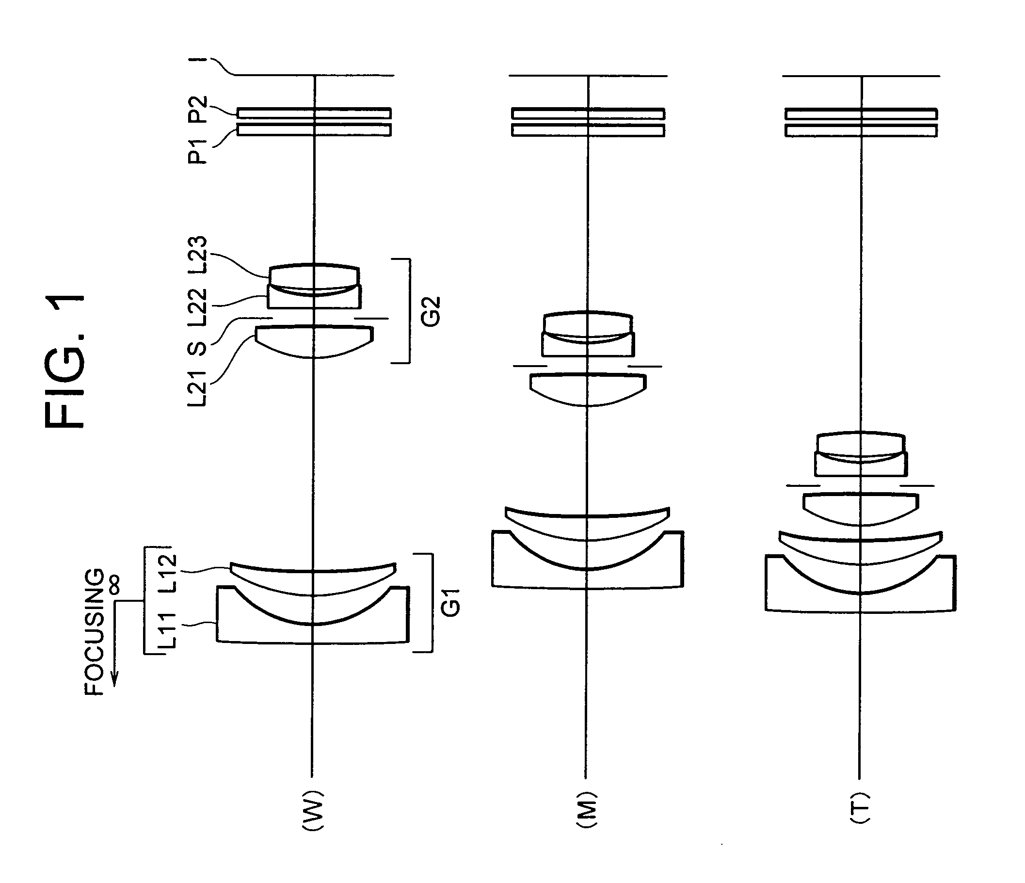
[0080]FIG. 1 is a diagram showing a lens configuration of a zoom lens system according to Example 1 of the present application in which W shows a wide-angle end state, M shows an intermediate focal length state, and T shows a telephoto end state. Reference symbols designating respective lenses used in the following explanations are listed only on the figure representing the wide-angle end state W. In the other focal length states, to list reference symbols is omitted.

[0081] The zoom lens system according to Example 1 of the present application is composed of, in order from an object, a first lens group G1 having negative refractive power, and a second lens group G2 having positive refractive power. Upon zooming from a wide-angle end state W to a telephoto end state T, a distance between the first lens group G1 and the second lens group G2 varies.

[0082] The first lens group G1 has negative refractive power as a whole and is composed of two lenses which are a negative meniscus lens ...

example 2

[0096]FIG. 4 is a diagram showing a lens configuration of a zoom lens system according to Example 2 of the present application in which W shows a wide-angle end state, M shows an inter mediate focal length state, and T shows a telephoto end state. Reference symbols designating respective lenses used in the following explanations are listed only on the figure representing the wide-angle end state W. In the other focal length states, to list reference symbols is omitted.

[0097] The zoom lens system according to Example 2 of the present application is composed of, in order from an object, a first lens group G1 having negative refractive power, and a second lens group G2 having positive refractive power. Upon zooming from a wide-angle end state W to a telephoto end state T, a distance between the first lens group G1 and the second lens group G2 varies.

[0098] The first lens group G1 has negative refractive power as a whole and is composed of two lenses which are a negative meniscus lens...

example 3

[0105]FIG. 7 is a diagram showing a lens configuration of a zoom lens system according to Example 3 of the present application in which W shows a wide-angle end state, M shows an inter mediate focal length state, and T shows a telephoto end state. Reference symbols designating respective lenses used in the following explanations are listed only on the figure representing the wide-angle end state W. In the other focal length states, to list reference symbols is omitted.

[0106] The zoom lens system according to Example 3 of the present application is composed of, in order from an object, a first lens group G1 having negative refractive power, and a second lens group G2 having positive refractive power. Upon zooming from a wide-angle end state W to a telephoto end state T, a distance between the first lens group G1 and the second lens group G2 varies.

[0107] The first lens group G1 has negative refractive power as a whole and is composed of two lenses which are a negative meniscus lens...


PUM


Abstract

Providing a zoom lens system having excellently correcting various aberrations with accomplishing to be compact, lightweight, and slim upon being retracted. The system is composed of, in order from an object, a first group having negative refractive power, and a second group having positive refractive power. Upon zooming from a wide-angle end state to a telephoto end state, a distance between the first group and the second group varies. The first group is composed of two lens elements which are, in order from the object, a negative lens having a concave surface facing an image, and a positive lens. The second group consists of three lens elements or less and includes, in order from the object, a positive lens, an aperture stop for defining an f-number, and a negative lens component including a negative lens and disposed to the image side of the aperture stop. Given conditions are satisfied.

Description

[0001] The disclosure of the following priority application is herein incorporated by reference: [0002] Japanese Patent Application No. 2005-282904 filed on Sep. 28, 2005. BACKGROUND OF THE INVENTION [0003] 1. Field of the Invention [0004] The present invention relates to a zoom lens system suitable for a camera. [0005] 2. Related Background Art [0006] With increasing miniaturizing trend of a digital camera, an optical system loaded thereon has strongly been required to be compact and lightweight to increase portability. With increasing integration of a solid-state imaging device, there has been required a zoom lens system capable of providing high contrast with respect to a higher spatial frequency. Japanese Patent Application Laid-Open No. 2003-287677 discloses a negative-leading zoom lens system suitable for a compact digital camera using such a solid-state imaging device. [0007] However, a zoom lens system disclosed in Japanese Patent Application Laid-Open No. 2003-287677 has re...

Claims


Application Information

Patent Timeline
Patent Type & Authority Applications(United States)
IPC IPC(8): G02B15/14
CPCG02B15/177G02B15/1425
Inventor MURATANI, MAMIYAMAMOTO, SAYAKO
Owner NIKON CORP
Why Eureka
Try Eureka