

Clam Type Mobile Phone
- Summary
- Abstract
- Description
- Claims
- Application Information
AI Technical Summary
Benefits of technology
Problems solved by technology
Method used
Image

Examples
Embodiment Construction
[0020] Reference will now be made in detail to the present preferred embodiments of the invention, examples of which are illustrated in the accompanying drawings. Wherever possible, the same reference numbers are used in the drawings and the description to refer to the same or like parts.
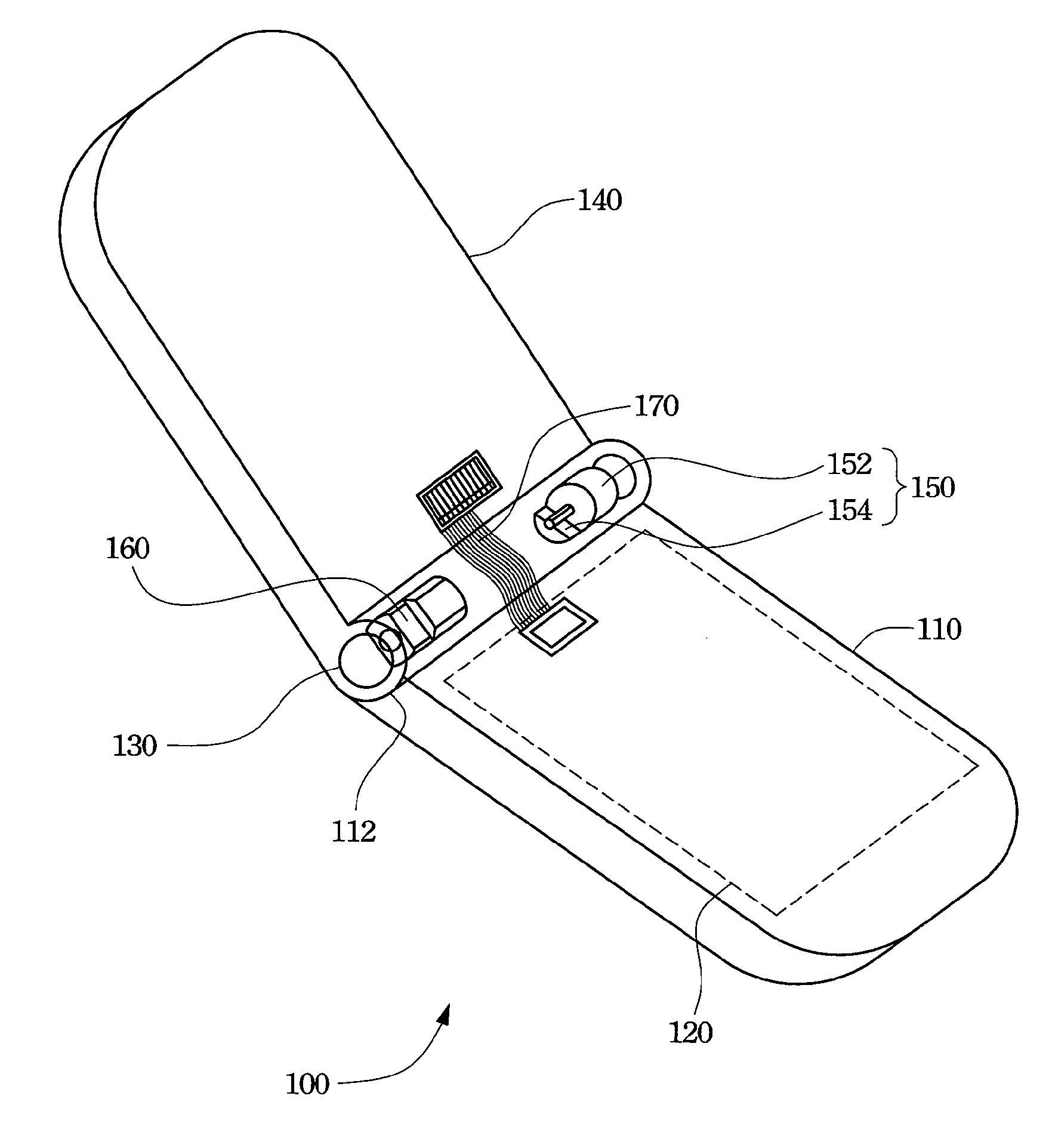
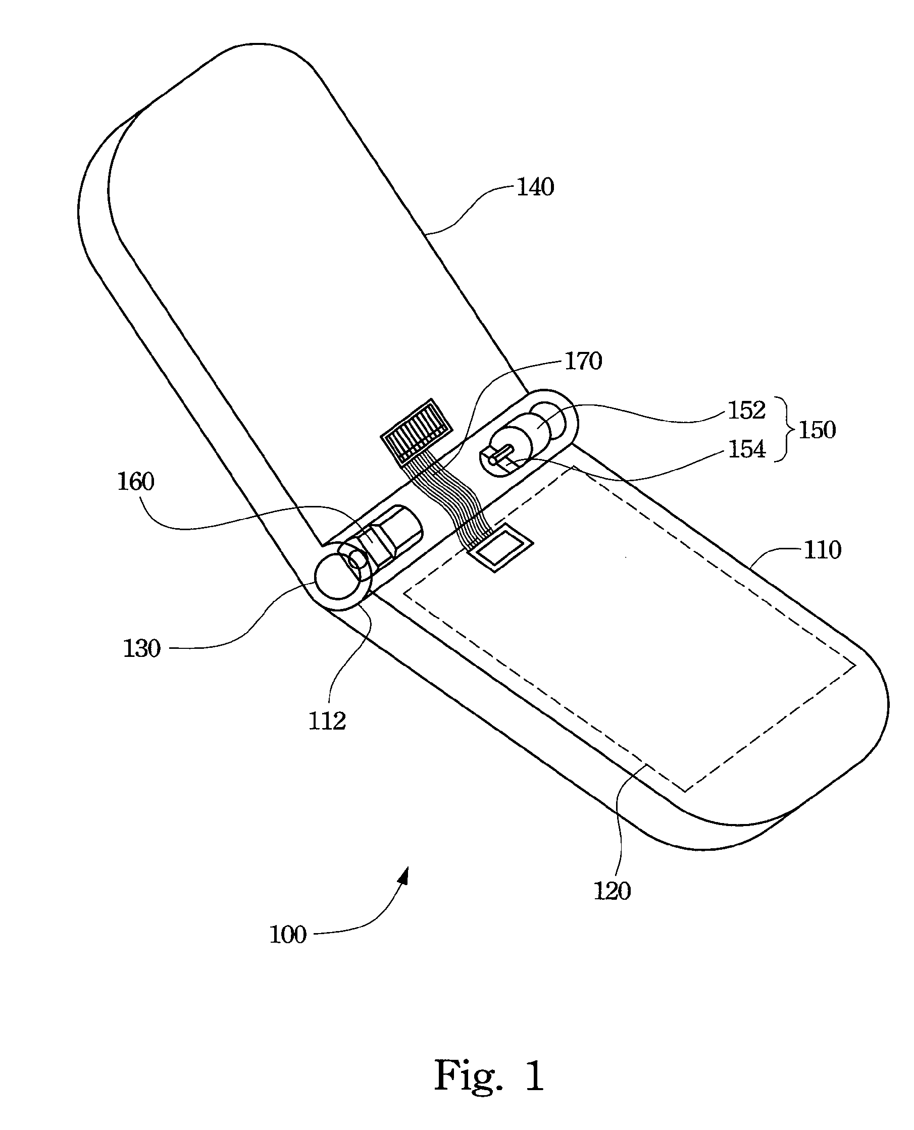
[0021] Reference is made to FIG. 1, which is a perspective drawing of a clam type mobile phone according to one preferred embodiment of the invention. In FIG. 1, a clam type mobile phone 100 including a base 110, a motherboard 120, a hinge seat 130, a display device 140 and a vibrator 150 is provided. The motherboard 120 is configured in the base 110. The hinge seat 130 is mounted on one side 112 of the base 110. The display device 140 is mounted on the hinge seat 130. The hinge seat 130 enables the display device 140 to rotate relative to the base 110. The vibrator 150 is configured in the hinge seat 130 and is electrically connected to the motherboard 120 for providing the clam type mobile phone ...
PUM
 Abstract
Description
Claims
Application Information