Suction brush for a vacuum cleaner

a vacuum cleaner and suction brush technology, applied in the direction of vacuum cleaners, cleaning equipment, domestic applications, etc., can solve the problems of deteriorating manipulation capability, inconvenience for users, and deteriorating manipulation ability of moving the suction brush, so as to improve the manipulation capability of the suction brush, minimize noise generation, and introduce smoothly

Inactive Publication Date: 2007-04-05
SAMSUNG GWANGJU ELECTRONICS CO LTD
View PDF8 Cites 0 Cited by
  • Summary
  • Abstract
  • Description
  • Claims
  • Application Information

AI Technical Summary

Benefits of technology

[0014] Because the air jetting path may comprise an air suction gap, a space formed between the top and bottom panels, and plural jetting holes for discharging the air to the surface to be cleaned, it is possible to improve the manipulation capability of the suction brush as the distance between the dust guide groove and the surface to be cleaned is increased by the air jetted from the air jetting path.
[0015] In addition, because the air suction gap is located at a position higher than that of the bottom side of the bottom panel, ambient air can be smoothly introduced into the air suction gap. Furthermore, because the air to be jetted through the jetting holes is absorbed from the bottom side of the body, which is not exposed to the outside, it is possible to minimize the noise generated when absorbing the air.

Problems solved by technology

However, if the suction brush is in close contact with the carpet, the manipulation capability for moving the suction brush is considerably deteriorated.
However, when cleaning a bristly area, a carpet or bedding, the dust guide groove 5 and the suction port 7 are still in close contact with the surface being cleaned, thereby still having the same inconvenience to the user.
Accordingly, the manipulation capability is deteriorated as the contacting force between the surface being cleaned and the suction brush is increased.
With this suction brush, however, because the air suction openings are exposed to the outside, noise is generated around the air suction openings as the ambient air is rapidly suctioned into the air suction openings.
Because the suction brush and the surface being cleaned (the surface of bedding) are still in close contact with each other, the manipulation capability of the suction brush is not improved.

Method used


Image

  • Suction brush for a vacuum cleaner
  • Suction brush for a vacuum cleaner
  • Suction brush for a vacuum cleaner

Examples


Embodiment Construction

[0024] Hereinbelow, certain embodiments of the present invention are described in detail with reference to accompanying drawings. In the following description, a detailed description of known functions and configurations incorporated herein will be omitted when it may make the subject matter of the present invention rather unclear.

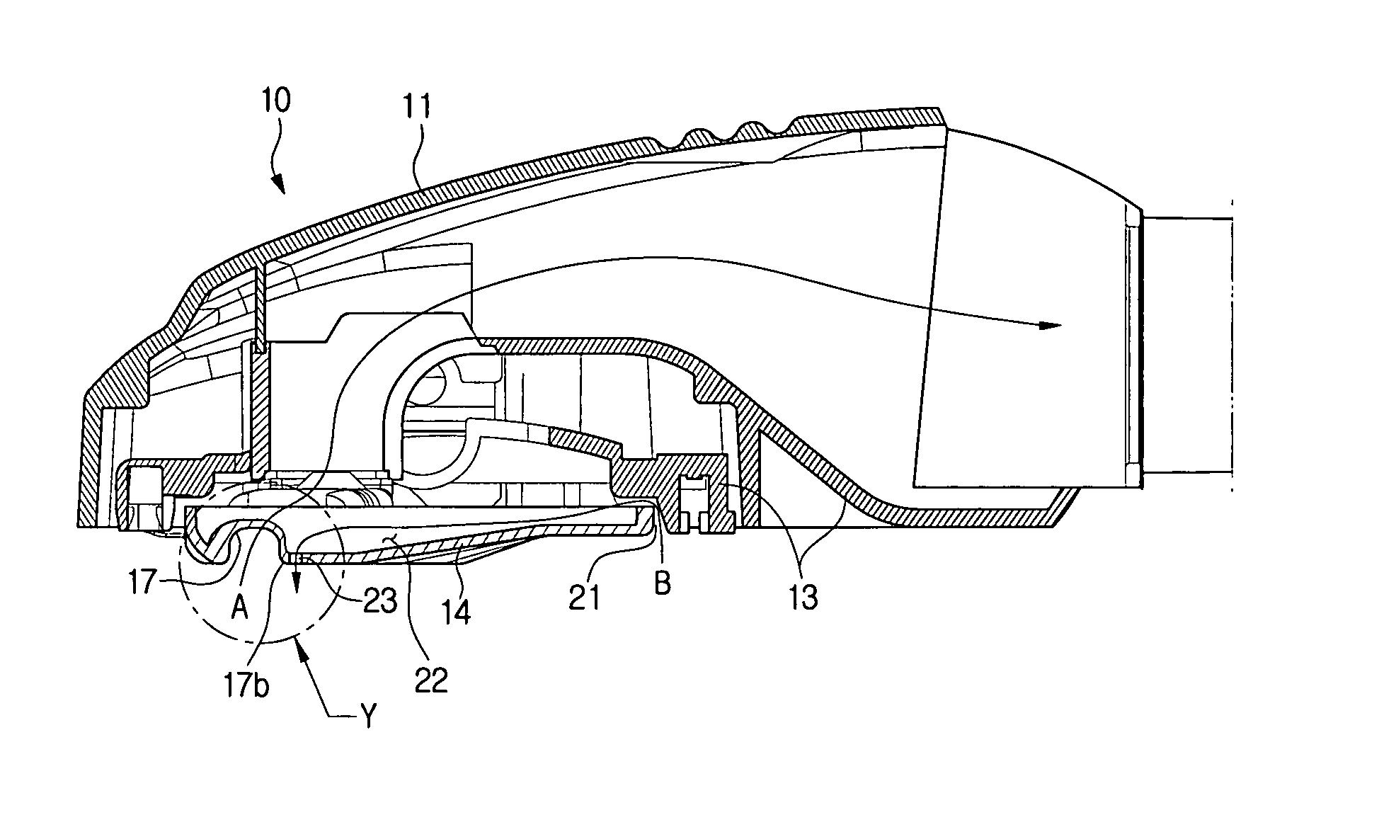
[0025]FIG. 2 is a partially cut-away perspective view illustrating an internal construction of a suction brush of a vacuum cleaner according to an embodiment of the present invention, FIG. 3 is a bottom view of the suction brush of FIG. 2, and FIG. 4A is a cross-sectional view taken along line X-X of FIG. 2, and FIG. 4B is a enlarged view of Y illustrated in FIG. 4A.

[0026] As shown in FIG. 2, the suction brush 10 of a vacuum cleaner according to an embodiment of the present invention has a body 15 which comprises a bottom panel 14 which contacts the surface to be cleaned, a top panel 13 located on the top of the bottom panel 14.

[0027] As shown in FIG. 3...


PUM


Abstract

A suction brush for a vacuum cleaner including a body, the bottom side of which is formed with a suction port; a cover for covering the top side of the body; and an air jetting path for absorbing ambient air from the bottom side of the body and jetting the air toward a surface to be cleaned, to space the bottom side from the surface to be cleaned.

Description

CROSS-REFERENCE TO RELATED APPLICATIONS [0001] This application claims the benefit of Korean Patent Application No. 2005-93114 filed on Oct. 4, 2005 with the Korean Intellectual Property Office, the disclosure of which is incorporated herein by reference FIELD OF THE INVENTION [0002] The present invention relates to a suction brush for a vacuum cleaner, and more particularly to a suction brush having improved manipulation capability. BACKGROUND OF THE INVENTION [0003] In general, a conventional suction brush for a vacuum cleaner has a suction port formed in the bottom thereof, to suction dust or dirt from a surface to be cleaned, and one or more dust guide grooves for guiding dust to the suction port. As seen in FIG. 1, the suction brush via a suction motor (not shown) absorbs dust together with ambient air through opposite ends 5a and 5b of a dust guide groove 5 when the bottom surface of the body 1 of the suction brush is in close contact with carpet. The dust and air introduced i...

Claims


Application Information

Patent Timeline
Patent Type & Authority Applications(United States)
IPC IPC(8): A47L9/02
CPCA47L7/06A47L9/02A47L9/08
Inventor SONG, HWA-GYULEE, HYUN-JUYANG, DONG-HOUNYOU, JAE-SUNKIM, JUNG-HYEONLEE, JUN-YOUNG
Owner SAMSUNG GWANGJU ELECTRONICS CO LTD
Why Eureka
Try Eureka