Method and apparatus for improved cooling of resistance welding cap

a technology of resistance welding cap and cooling cap, which is applied in the direction of cooled electrodes, manufacturing tools, electrode features, etc., can solve the problems of welding electrode wear and replacemen

Active Publication Date: 2007-04-05
GM GLOBAL TECH OPERATIONS LLC +1
View PDF6 Cites 3 Cited by
  • Summary
  • Abstract
  • Description
  • Claims
  • Application Information

AI Technical Summary

Problems solved by technology

Over time the welding electrodes wear and must be replaced.

Method used


Image

  • Method and apparatus for improved cooling of resistance welding cap
  • Method and apparatus for improved cooling of resistance welding cap
  • Method and apparatus for improved cooling of resistance welding cap

Examples


Embodiment Construction

[0023] The following description of certain exemplary embodiment(s) is merely exemplary in nature and is in no way intended to limit the invention, its application, or uses.

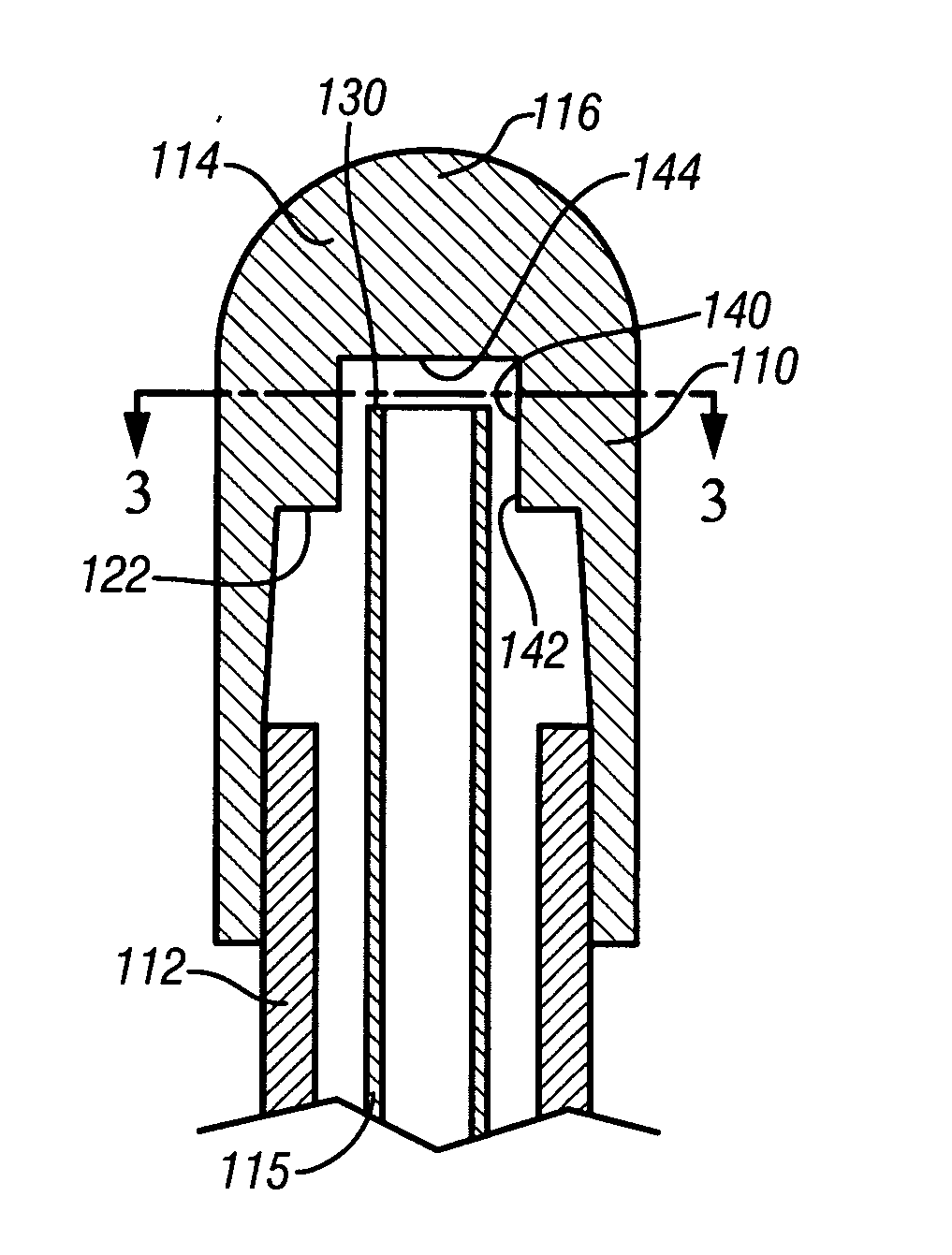
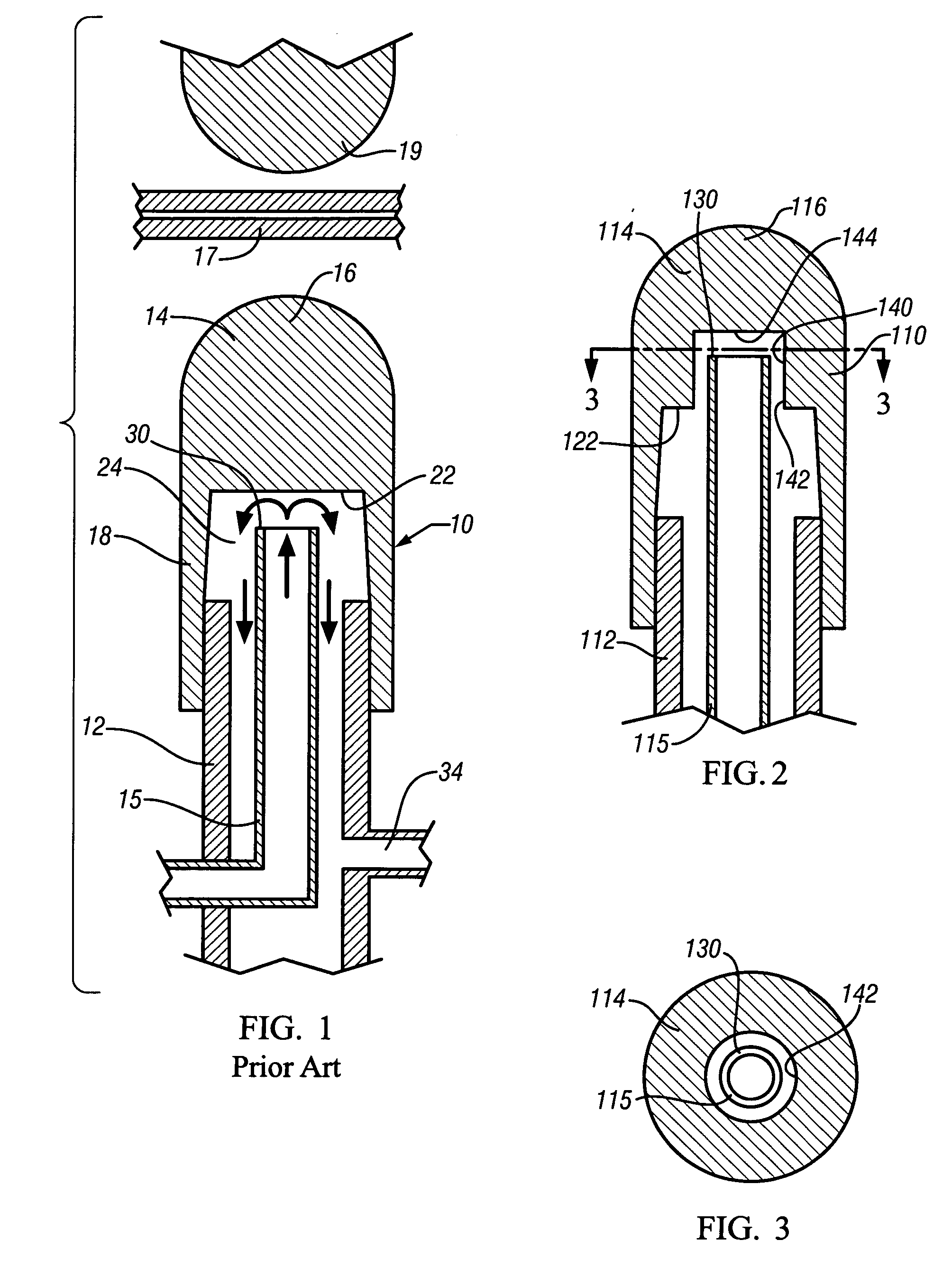
[0024] According to FIG. 1 a welding electrode is generally shown at 10 and includes a shank 12, a weld cap 14, and a coolant supply tube 15. The shank 12 is suitably attached to a welder, not shown.

[0025] The weld cap 14 is preferably of copper, or a copper alloy, and includes a cap tip 16 which will be pressed against a work piece 17, comprised of a pair of panels, that are to be welded together. An opposing electrode 19 will be pressed against the opposite side of work piece 17. The weld cap 14 also includes a cylindrical skirt 18 that extends from the cap tip 16 and closely surrounds the shank 12. The skirt 18 is shown as press fit onto the shank 12, but in the alternative may have threads that screw onto mating threads on the shank 12, but are not shown. As seen in FIG. 1 the cap tip 16 has an underside 22...


PUM

PropertyMeasurementUnit
sizesaaaaaaaaaa
sizesaaaaaaaaaa
areaaaaaaaaaaa

Abstract

According to the invention a hollow cylindrical shank of electrically conducting metal is connected to a resistance welder. A coolant supply tube passes through the shank and has an interior coolant supply passage. The coolant supply tube has an outer diameter less than the inner diameter of the hollow cylindrical shank. A weld cap seats on the shank and has a cap tip and a cap skirt that depends from the cap tip and is attached to the shank. An underside of the cap tip faces the shank and the supply tube. A coolant receiving bore formed into the underside of the weld cap extends into the cap tip to receive the coolant supply tube part way into the bore. The bore formed into the underside of the cap tip defines a bore sidewall that provides added area of heat transfer contact between the coolant and the cap tip.

Description

FIELD OF THE INVENTION [0001] The present invention relates to a method and apparatus for improving the cooling of a resistance welding cap. BACKGROUND OF THE INVENTION [0002] It is well known to weld together two sheets of metal using a resistance welding unit. Welding electrodes are applied to opposite sides of the metal panels and current is conducted through the electrodes to weld and fuse the panels together and form a spot weld. Over time the welding electrodes wear and must be replaced. [0003] Accordingly it is well known that the welding electrode include a shank that is connected to the resistance welder to receive the weld current, and a replaceable weld cap, typically of copper alloy, that is either press fit or threaded onto or into the shank to permit removal and replacement of the worn weld cap. [0004] It is also well known that the efficiency of the resistance welding process is improved by circulating a coolant, such as water, through the shank to cool the weld cap. ...

Claims


Application Information

Patent Timeline
Patent Type & Authority Applications(United States)
IPC IPC(8): B23K11/30
CPCB23K11/3054
Inventor STEVENSON, ROBINWANG, PEI-CHUNGKARAGOULIS, MICHAEL J.TSAI, HAI-LUNG
Owner GM GLOBAL TECH OPERATIONS LLC
Why Eureka
Try Eureka