Parachute with skirt reefing system

a technology of reefing system and parachute, which is applied in the field of parachute with a skirt reefing system, can solve the problems of increasing the cost of such pyrotechnic cutters, affecting the overall annual cost of many cargo airdrops, and the relative high cost of the plurality of pyrotechnic cutters

Inactive Publication Date: 2007-04-05
UNITED STATES OF AMERICA THE AS REPRESENTED BY THE SEC OF THE ARMY
View PDF14 Cites 5 Cited by
  • Summary
  • Abstract
  • Description
  • Claims
  • Application Information

AI Technical Summary

Benefits of technology

[0008] In one aspect, the present invention is directed to a parachute system comprising a canopy having a skirt and an apex, a plurality of reefing rings attached to the skirt, and a plurality of suspension lines. Each suspension line has a first end attached to the skirt near a corresponding reefing ring and a second end opposite the first end. All of the second ends of the suspension lines are connected together to define a confluence point. The parachute system further comprises a center line that is attached to and between the apex of the canopy and the confluence point, and a single reefing line cutter that is attached to the center line. The single reefing line cutter is activated after a predetermined amount of time has elapsed. The parachute system further includes a first reefing line that extends through a first group of the plurality of reefing rings. The first reefing line has a first end attached to the single reefing line cutter and a second end attached to the skirt at a first predetermined location. The parachute system further includes a second reefing line that extends through a second group of the plurality of reefing rings. The second group of reefing rings is approximately opposite the first group of reefing rings. The second reefing line has a first end attached to the single reefing line cutter and a second end attached to the skirt at a second predetermined location that is across from the first predetermined location. When the parachute system is deployed, the canopy opens to an initial circumference determined by the summation of the lengths of the first and second reefing lines. When the single reefing line cutter is activated, the first and second reefing lines are released thereby allowing full inflation of the canopy.
[0009] In a related aspect, the present invention is directed to a parachute system having a canopy which has skirt and an apex. The parachute system further comprises a plurality of reefing rings attached to the skirt, and a plurality of suspension lines. Each suspension line has a first end attached to the skirt near a corresponding reefing ring and a second end opposite the first end. The parachute system further includes a plurality of risers. Each riser has a first end attached to the second end of a corresponding suspension line. Each riser includes a second end opposite the first end of the riser. All of the second ends of the risers are connected together to define a confluence point. The parachute system also includes a center line attached to and between the apex of the canopy and the confluence point, and a single reefing line cutter that is attached to the center line. The single reefing line cutter is activated after a predetermined amount of time has elapsed. The parachute system further includes a first reefing line that extends through a first group of the plurality of reefing rings. The first reefing line has a first end attached to the single reefing line cutter and a second end attached to the skirt at a first predetermined location. The parachute system further includes a second reefing line that extends through a second group of the plurality of reefing rings. The second group of reefing rings is approximately opposite the first group of reefing rings. The second reefing line has a first end that is attached to the single reefing line cutter and a second end that is attached to the skirt at a second predetermined location that is across from the first predetermined location. When the parachute system is deployed, the canopy opens to an initial circumference that is determined by the summation of the lengths of the first and second reefing lines. When the single reefing line cutter is activated, the first and second reefing lines are released thereby allowing full inflation of the canopy.

Problems solved by technology

A disadvantage of such prior art skirt reefing technique is the relatively high cost resulting from the use of a plurality of pyrotechnic cutters.
The cost of such pyrotechnic cutters has steadily increased over the years and such cost contributes to the overall annual cost of conducting many cargo airdrops.
Therefore, the accumulated cost for using so many pyrotechnic cutters on these cargo parachutes is very significant.

Method used


Image

  • Parachute with skirt reefing system
  • Parachute with skirt reefing system
  • Parachute with skirt reefing system

Examples


Embodiment Construction

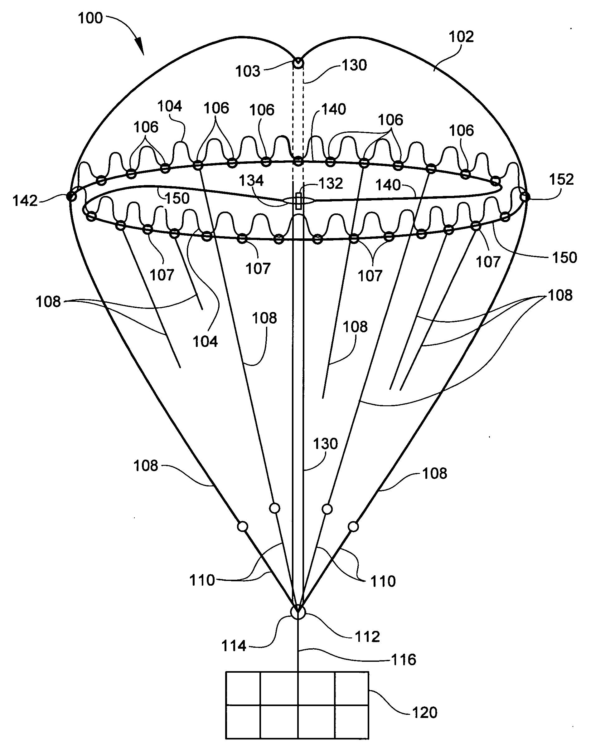
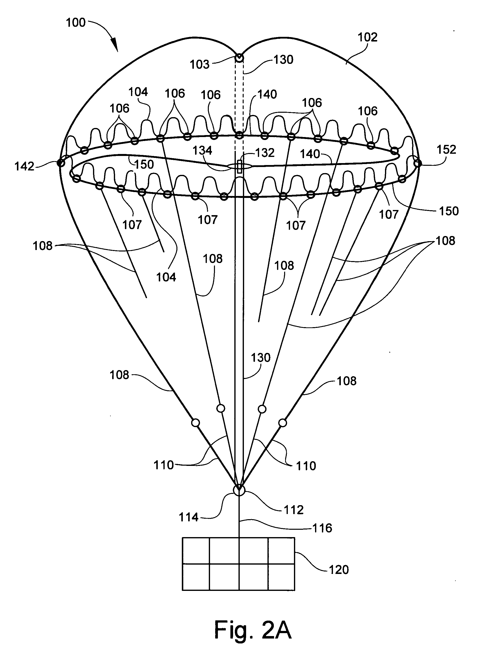
[0014] Referring to FIGS. 2A and 2B, there is shown parachute system 100 of the present invention. Parachute system 100 generally comprises canopy 102 having apex 103 and skirt 104. Parachute system 100 further includes a first plurality of reefing rings 106 and a second plurality of reefing rings 107. Reefing rings 106 and 107 are attached to skirt 104. In a preferred embodiment, the reefing rings 107 are oppositely located with respect to reefing rings 106. Parachute system 100 includes a plurality of suspension lines 108. For purposes of clarity, some of the suspension lines 108 are either not shown or are only partially shown. Each suspension line 108 has a first end attached to skirt 104 near a corresponding reefing ring 106 or reefing ring 107. Each suspension line 108 also has a second end opposite its first end. In one embodiment, the second end of each suspension line 108 is attached to one end of a corresponding riser 110. The opposite ends of risers 110 are connected toge...


PUM


Abstract

A parachute system has a canopy, suspension lines that extend from the canopy skirt to a confluence point, and a center line that is attached to and between the apex of the canopy and the confluence point. A single reefing line cutter is attached to the center line and is activated after a predetermined amount of time has elapsed. A first reefing line extends through a first group of reefing rings wherein one end of the first reefing line is attached to the single reefing line cutter and the opposite end is attached to the canopy skirt at a first predetermined location. A second reefing line extends through a second group of reefing rings that is opposite the first group of reefing rings. The second reefing line has one end attached to the single reefing line cutter and an opposite end attached to the canopy skirt at a second predetermined location that is across from the first predetermined location. The canopy opens to an initial circumference that is determined by the summation of the lengths of the first and second reefing lines. When the reefing line cutter is activated, the reefing line cutter releases the first and second reefing lines so as to allow full inflation of the canopy.

Description

STATEMENT OF GOVERNMENT INTEREST [0001] The invention described herein may be manufactured and used by the U.S. Government for Governmental purposes without the payment of any royalties thereon.BACKGROUND OF THE INVENTION [0002] 1. Field of the Invention [0003] The present invention generally relates to a parachute with a skirt reefing system. [0004] 2. Description of the Related Art [0005] Large cargo parachutes typically have diameters of about one hundred feet and are made of solid cloth. Due to the large amount of canopy fabric, the opening process of such relatively large cargo parachutes is typically controlled in order to allow the canopy to open in stages thereby ensuring proper and safe inflation. A common technique used to control the opening process of the canopy is skirt reefing. Skirt reefing involves the use of a reefing line or cord with a length that is less than the circumference of the canopy skirt when the canopy is fully opened. The reefing line is attached to th...

Claims


Application Information

Patent Timeline
Patent Type & Authority Applications(United States)
IPC IPC(8): B64D17/00
CPCB64D17/343
Inventor LEE, CALVIN K.
Owner UNITED STATES OF AMERICA THE AS REPRESENTED BY THE SEC OF THE ARMY
Why Eureka
Try Eureka