Liquid crystal display device

a display device and liquid crystal technology, applied in the field of liquid crystal display devices, can solve the problems the difficulty of restricting the omnidirectional viewing angle, etc., and achieve the effect of increasing the thickness, weight and power consumption of the entire display device, and not increasing the cost of the display devi

Inactive Publication Date: 2007-04-05
JAPAN DISPLAY CENTRAL CO LTD
View PDF6 Cites 27 Cited by
  • Summary
  • Abstract
  • Description
  • Claims
  • Application Information

AI Technical Summary

Benefits of technology

[0008] The present invention has been made in consideration of the above-described problems, and the object of the invention is to provide a liquid crystal display device which is capable of controlling viewing angles without increasing the cost of the display device or increasing the thickness, weight and power consumption of the entire display device.
[0010] The present invention can provide a liquid crystal display device which is capable of controlling viewing angles without increasing the cost of the display device or increasing the thickness, weight and power consumption of the entire display device.

Problems solved by technology

According to the structure of Patent Document 1, however, it is difficult to restrict omnidirectional viewing angles, because of the effect of viewing angle characteristics of the liquid crystal plate for varying the viewing angle.
Moreover, the addition of the liquid crystal plate for varying the viewing angle leads to demerits such as an increase in cost, thickness, weight and power consumption.

Method used


Image

  • Liquid crystal display device
  • Liquid crystal display device
  • Liquid crystal display device

Examples


other embodiment 1

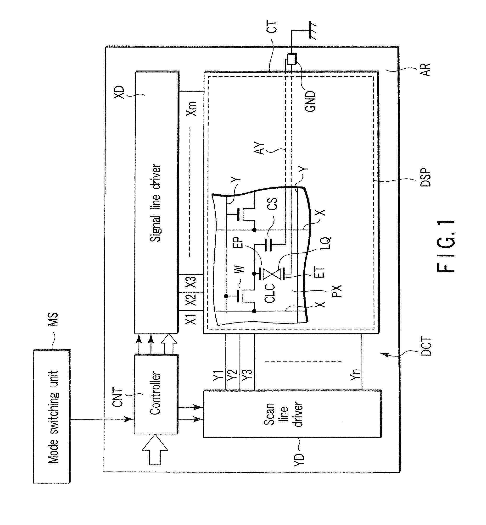
[0076] In the above-described embodiment, when the controller CNT converts first image data of display image, which is displayed in the gradation range of 0 to n−1, to second image data in the gradation range of i to j, the controller CNT assigns two gray levels of the first image data to one gray level of the second image data. The invention, however, is not limited to this example. As regards the number of gray levels of the first image data, which are to be assigned to the second image data, the first data may be converted such that the number of gray levels on the higher gradation side of the first image data is smaller than the number of gray levels on the lower gradation side of the first image data.

[0077] For example, as shown in FIG. 9, the controller CNT converts first image data, which is displayed in the gradation range of 256 gray levels from level 0 to level 255, to second image data of a 24 gray-level range between 232 and 255 (i.e. about 10% of the gradation range of...

other embodiment 2

[0080] The liquid crystal display panel LPN includes a plurality of kinds of color pixels in the case where the display device is applied not only to display of character images, but also to display of color images such as ordinary video. For example, the liquid crystal display panel LPN includes first color pixels which display an image in the gradation range of an n-number of gray levels in a first color, and second color pixels which display an image in the gradation range of the n-number of gray levels in a second color with a lower relative visibility than the first color. In this structure, when the narrow viewing angle mode is to be realized, the controller CNT does not need to convert, with respect to both the first and second color pixels, the first image data of a display image, which is displayed in the gradation range of gray levels 0 to n−1, uniformly to image data of the same gradation range. Specifically, in the narrow viewing angle mode, the controller CNT displays a...

other embodiment 3

[0083] The controller CNT may convert a part of first image data of a display image, which is displayed in a gradation range of 0 to n−1, to second image data of the display image, which is displayed in a gradation range of i to j.


PUM


Abstract

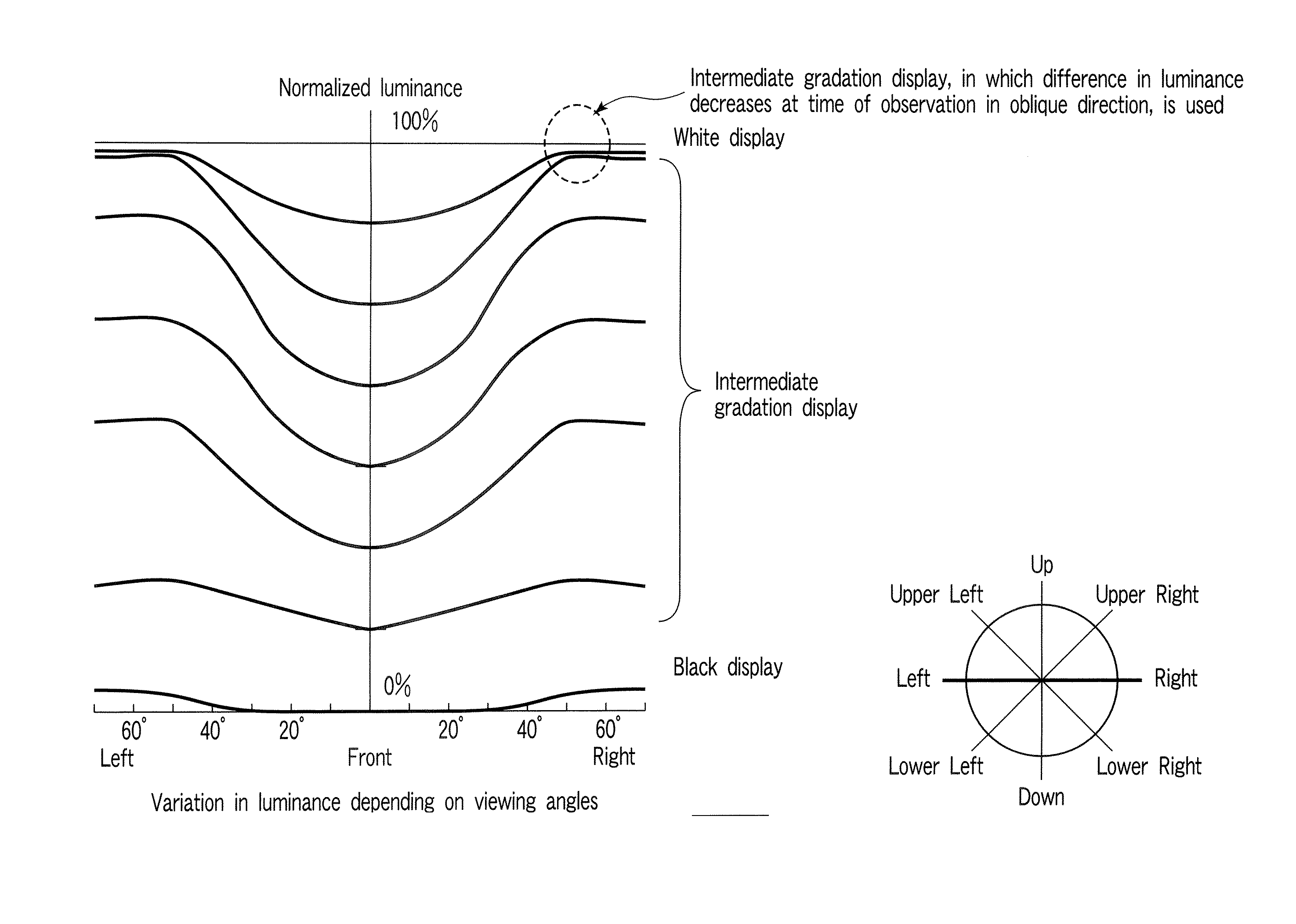
A liquid crystal display device has a gradation display function of at least an n-number of gray levels and has a viewing angle characteristic of Mi / Mj≦1.3 in a case where a display luminance range in a normal direction to a display surface in a gradation range of predetermined gray levels i to j is Li to Lj and a display luminance range in an oblique viewing-angle direction of 30° or more is Mi to Mj (where n, i and j are real numbers, and n≧i>j≧0). The liquid crystal display device has a display mode in which a display image is displayed with a display luminance range of the display image being limited to Li to Lj.

Description

CROSS-REFERENCE TO RELATED APPLICATIONS [0001] This application is based upon and claims the benefit of priority from prior Japanese Patent Applications No. 2005-257954, filed Sep. 6, 2005; and No. 2006-062860, filed Mar. 8, 2006, the entire contents of both of which are incorporated herein by reference. BACKGROUND OF THE INVENTION [0002] 1. Field of the Invention [0003] The present invention relates generally to a liquid crystal display device, and more particularly to a liquid crystal display device which is configured to be capable of realizing both a wide viewing angle and a narrow viewing angle. [0004] 2. Description of the Related Art [0005] In recent years, mobile phones, which can display mail and images, have widely been used. In using such mobile phones, there have been increasing needs for preventing a displayed image from being peeped at by persons around the user. [0006] To satisfy such needs, Jpn. Pat. Appln. KOKAI Publication No. 2004-062094 (Patent Document 1), for i...

Claims


Application Information

Patent Timeline
Patent Type & Authority Applications(United States)
IPC IPC(8): G09G3/36
CPCG02F1/1393G09G3/2007G09G3/3648G09G2320/0271G09G2320/0285G09G2320/068G09G2330/021G09G2360/16G02F1/133
Inventor YAMADA, YOSHITAKAWATANABE, RYOICHIKINOSHITA, MASAKIWATANABE, YOSHIHIROFUJIBAYASHI, SADAYASUYOSHIDA, NORIHIRO
Owner JAPAN DISPLAY CENTRAL CO LTD
Why Eureka
Try Eureka