
Holographic recording medium

a recording medium and holographic technology, applied in the field of holographic recording mediums, can solve the problems of not being able to perform normal recording/reproducing, unable to allocate the address like the conventional mo, and destroying existing data or data which is different from the target data, etc., to achieve the effect of improving the detection precision of the recording

Inactive Publication Date: 2007-04-05
FUJITSU LTD
View PDF2 Cites 6 Cited by
  • Summary
  • Abstract
  • Description
  • Claims
  • Application Information

AI Technical Summary

Benefits of technology

[0017] The present invention provides a holographic recording medium which includes a track in which position information to specify a recording position and a reproducing position of page data is formed, the position information of the track being formed of position detection patterns, the position detection patterns each including a first detection mark row including center pits arranged at predetermined intervals; and a second detection mark row including side marks arranged at the same intervals as the intervals of the center pits, the side marks having lengths substantially corresponding to integral multiples of the intervals of the center pits, wherein the second detection mark row is arranged adjacent to the first detection mark row such that both ends of the side marks are arranged so as to correspond to the center pits in a track width direction, and page data is recorded and reproduced on the basis of positions of the center pits or positions of the ends of the side marks. Thus, it is possible to improve a detection precision of a recording and reproducing position.

Problems solved by technology

If the recording is performed before the target address and the present address coincide with each other, existing data could be destroyed or data which is different from the target data is read out due to a defect of reproduction.
As a result, normal recording / reproducing cannot be performed.
Therefore, if an address is allocated to one recording unit like the conventional MO, since a ratio occupied by recording region to be used for recording the address information is increased, it is actually difficult to allocate the address like the conventional MO.
Thus, according to the conventional holographic recording, it is difficult to confirm that the target address coincides with the present address every recording unit before the data is recorded or reproduced like an address detection process of the conventional MO.
However, since the recording capacity of the page information which is one unit for the recording / reproducing is very large such as hundreds of megabytes, it takes a lot of time to reproduce the page information itself.
That is, since it is found that the address information is different from the target address after the page data containing the address information is reproduced, which takes a lot of time, a waste time is consumed for the reproducing, so that it takes a lot of time to perform the reproducing process substantially.

Method used


Image

  • Holographic recording medium
  • Holographic recording medium
  • Holographic recording medium

Examples


first embodiment

(Constitution of Holographic Recording Medium of the Present Invention)

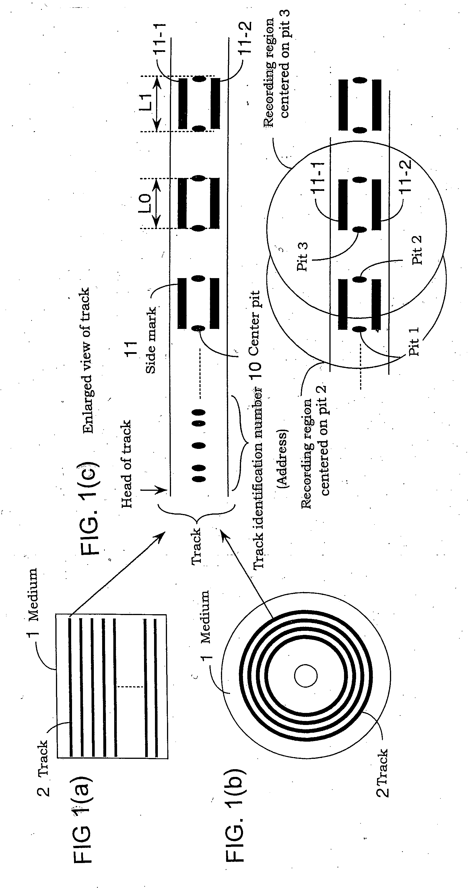
[0048]FIG. 1 shows a constitution of a holographic recording medium according to one embodiment of the present invention.

[0049] In FIG. 1, (a) is a plan view showing a rectangular card-shaped medium 1, and (b) is a plan view showing a disk-shaped medium 1.

[0050] Each medium has a track 2 in which position information for finding a recording position or a reproducing position has been previously formed on a medium surface. The position information contains track identification numbers and position detection patterns. The track identification number and the position detection pattern are formed at the time of manufacturing as fixed information which cannot changed before shipping.

[0051] A plurality of linear tracks 2 are formed in parallel in (a) of FIG. 1.

[0052] A plurality of tracks 2 are concentrically formed in (b) of FIG. 1.

[0053] For example, when a recording request of data into a certain logical addre...

second embodiment

(Constitution of Medium of The Present Invention)

[0195]FIG. 15 shows a constitution of position detection patterns of a holographic medium according to a second embodiment of the present invention.

[0196] In FIG. 15, (c) is an enlarged view showing a region of three adjacent tracks 2 formed on the medium. Also in FIG. 15, (a) and (b) show medium configuration examples. According to the second embodiment, the position detection patterns include one row of patterns which include a plurality of guide pitches, and computer-generated hologram patterns.

[0197] Referring to (c) of FIG. 15, one row of guide pitches 80 are formed in a track direction in almost the center of each track 2 at regular intervals in its width direction.

[0198] The guide pitches 80 are to confirm a position in the track and formed as projections or recesses, in which address information is not contained.

[0199] The position of each guide pitch is a reference position of a region in which the page data is recorded / ...

third embodiment

(Constitution of Medium of the Present Invention)

[0219]FIG. 17 shows a constitution of position detection patterns of a holographic medium according to a third embodiment of the present invention.

[0220] Here, the position detection patterns in a track 2 include three rows of patterns 15, 16-1 and 16-2.

[0221] Although a point that the three rows of patterns are formed is similar to that in (c) of FIG. 1, a point that one of the side marks 16-1 and 16-2 includes a plurality of pits is different.

[0222] The center marks 15 in the center of the track 2 are arranged at regular intervals and they have an indented configuration and have no address information similar to the center pit shown in (c) of FIG. 1, which may be used both for focus control and tracking control.

[0223] The rows of the side marks 16-1 and 16-2 corresponding to the second detection mark row are arranged in the vicinity of the center marks 15 provided at regular intervals in a track width direction. Each side mark ...


PUM

PropertyMeasurementUnit
lengthaaaaaaaaaa
distanceaaaaaaaaaa
lengthsaaaaaaaaaa

Abstract

This invention is a holographic recording medium including a track in which position information to specify a recording position and a reproducing position of page data is formed. The position information of the track is formed of position detection patterns. The position detection patterns each including a first detection mark row including center pits arranged at predetermined intervals; and a second detection mark row including side marks arranged at the same intervals as the intervals of the center pits, the side marks having lengths substantially corresponding to integral multiples of the intervals of the center pits. The second detection mark row is arranged adjacent to the first detection mark row such that both ends of the side marks are arranged so as to correspond to the center pits in a track width direction, and page data is recorded and reproduced on the basis of positions of the center pits or positions of the ends of the side marks.

Description

CROSS-REFERENCE TO RELATED APPLICATIONS [0001] This application is related to Japanese application No. 2005-290341 filed on Oct. 3, 2005, whose priority is claimed under 35 USC § 119, the disclosure of which is incorporated by reference in its entirety. BACKGROUND OF THE INVENTION [0002] 1. Field of the Invention [0003] The present invention relates to a holographic recording medium and more particularly, to a medium in which holographic recording / reproducing can be performed after a recording position or a reproducing position is detected in the medium. [0004] 2. Description of the Related Art [0005] According to a conventional magneto-optical recording medium (such as MO), while address information previously recorded on the medium is detected, a seek operation is performed in which an optical component and the like is moved by a distance corresponding to a difference between a detected present address and a target address in which recording (or reproducing) is to be performed, an...

Claims


Application Information

Patent Timeline
Patent Type & Authority Applications(United States)
IPC IPC(8): G11B7/00
CPCG11B7/0065G11B7/00772G11B7/00781G11B7/24044G11B20/10G11B20/1217G11B27/24G11B2020/1267G11B2020/1274G11B2220/2504
Inventor UCHIDA, AKIYOSHIKANAOKA, TOSHIKAZU
Owner FUJITSU LTD
Learn More