Method and apparatus for estimating a local impedance factor

a local impedance factor and factor technology, applied in the field of method and apparatus for estimating local impedance factors, can solve the problems of non-therapeutic heating in these removed locations, not necessarily indicative of an appropriate level of treatment, applied current and voltage, etc., and achieve the effect of better determining appropriate therapeutic energy levels

Inactive Publication Date: 2007-04-05
THERMAGE INC
View PDF94 Cites 82 Cited by
  • Summary
  • Abstract
  • Description
  • Claims
  • Application Information

AI Technical Summary

Benefits of technology

[0008] The invention overcomes the problems outlined above, as well as other problems with conventional treatment methods and devices, and provides improved methods and electromagnetic energy devices for the treatment of patients at specific patient treatment zones. In order to better determine appropriate therapeutic energy levels, the invention estimates local impedance factors associated with respective patient treatment zones, and uses these estimated factors to determine the energy levels. Generally, the methods of patient treatment of the invention comprise sending first and second measurement signals partially through a patient treatment zone to determine corresponding measurement values and using the determined measurement values to estimate the local impedance factor.

Problems solved by technology

However, merely sensing applied currents and voltages and delivering controlled amounts of energy is not necessarily indicative of an appropriate level of treatment being applied to each patient because each patient generally presents varying physical properties that are uniquely effected by the applied energy.
Another part of the delivered energy is absorbed by the patient in locations remote from the treatment zone, which results in non-therapeutic heating in these removed locations.
When the local impedance of the treatment zone is larger, excessive energy may be delivered to the treatment zone, which may damage the tissue.
Conversely, when the local impedance of the treatment zone is smaller, insufficient energy may be delivered to the treatment zone so that the desired therapeutic result (e.g., tissue tightening) is not achieved.
Reliance on patient feedback is disadvantageous because, on one hand, the amount of energy delivered to a patient with a low tolerance for pain may be non-therapeutic.
On the other hand, excessive energy may be delivered to a patient that is overly pain-tolerant based on the lack of a verbalized pain feedback.

Method used


Image

  • Method and apparatus for estimating a local impedance factor
  • Method and apparatus for estimating a local impedance factor
  • Method and apparatus for estimating a local impedance factor

Examples


Embodiment Construction

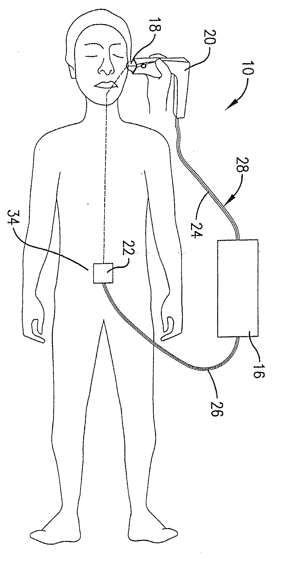
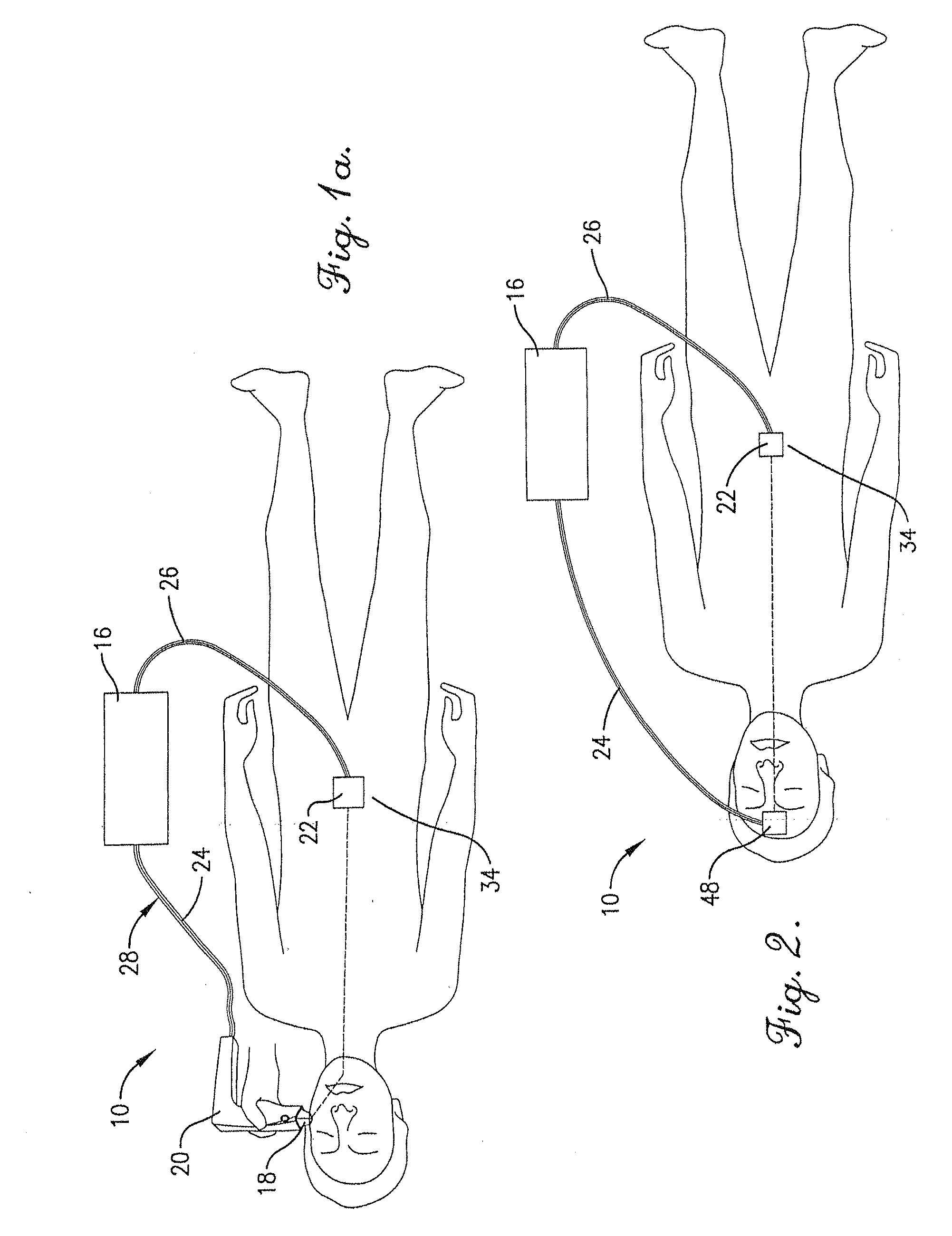
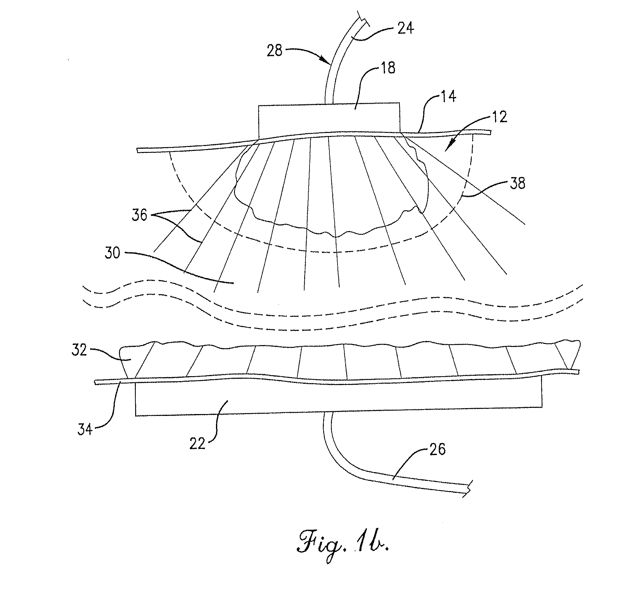
[0025] With reference to FIGS. 1a, 1b, and 5, a system 1O generally includes a generator 16 for generating a treatment signal and one or more measurement signals, a treatment electrode 18 which may be mounted on handpiece 20, and a second return electrode 22. The electrodes 18, 22 are coupled with the generator 16 via cables 24, 26, respectively. System 10 may be used to perform any therapeutic, medical, and / or cosmetic-related treatment for which it is suited.

[0026] Generator 16 may include other elements in addition to the signal generation elements, such as a controller 44 and at least one sensor 46. Sensor 46 may detect any one of any of signal current, voltage, resistance, impedance, and / or other signal parameters. The controller 44 and sensor 46 may be integral within the same housing as other elements of the generator 16, such as within a common generator housing, or the controller 44, sensor 46, and other generator elements, such as the signal generating elements, may be po...


PUM


Abstract

Method and apparatus for determining local impedance factors in an electromagnetic energy system for treating patients is disclosed. Respective measurement signals are sent through a patient treatment zone and a local impedance factor is estimated based upon the measurement signals. The estimated impedance factor is used to determine appropriate therapeutic levels of energy for patient treatment.

Description

CROSS-REFERENCE TO RELATED APPLICATIONS [0001] This application claims the benefit of U.S. Provisional Application Ser. No. 60 / 723,695 filed Oct. 5, 2005, the disclosure of which is hereby incorporated by reference herein in its entirety.FIELD OF THE INVENTION [0002] The invention relates to method and apparatus for estimating local impedance factors. More particularly, the invention relates to method and apparatus for determining a local impedance factor in an electromagnetic energy delivery device used to non-invasively treat patients. BACKGROUND OF THE INVENTION [0003] Electromagnetic energy delivery devices are often utilized to treat patients for various medical, cosmetic, and therapeutic reasons. For example, such devices may be utilized to heat tissue to within a selected temperature range to produce a desired effect, such as improving the appearance of the patient by removing or reducing wrinkles, tightening skin, removing hair, etc. Such devices generate a signal, such as a...

Claims


Application Information

Patent Timeline
Patent Type & Authority Applications(United States)
IPC IPC(8): A61F2/00
CPCA61B18/1206A61B2018/00702A61B2018/00875
Inventor WEBER, BRYANPOPE, KARLLEVINSON, MITCHELL
Owner THERMAGE INC
Why Eureka
Try Eureka