Ultrasonic virtual mouse

a virtual mouse and ultrasonic technology, applied in the field of ultrasonic virtual mouse, can solve the problems of user dissatisfaction with the maneuverability, ineffectiveness of the mouse, loss of profits,

Inactive Publication Date: 2007-04-19
AVAGO TECH ECBU IP (SINGAPORE) PTE LTD
View PDF5 Cites 34 Cited by
  • Summary
  • Abstract
  • Description
  • Claims
  • Application Information

AI Technical Summary

Benefits of technology

[0008] In a further embodiment, the processor is operable to detect a click event based on the reflected ultrasonic signals. For example, in one embodiment, the processor is operable to detect a cli...

Problems solved by technology

Although the mouse is an adequate cursor control device for many applications, in environments in which the mouse must operate in a limited workspace, users are generally dissatisfied with the maneuverability, and therefore, effectiveness of the mouse.
In addition, in some situations, it may be undesirable and/or inefficient for a user to remove his or her hand from the keyboard in order to control the mouse.
For example, if the user is a stockbroker, an employee responsible for handling customer service matters or other user that is required to both access and enter information quickly, any delays caused by the user moving his or her hand between the keyboard and th...

Method used


Image

  • Ultrasonic virtual mouse
  • Ultrasonic virtual mouse
  • Ultrasonic virtual mouse

Examples


Embodiment Construction

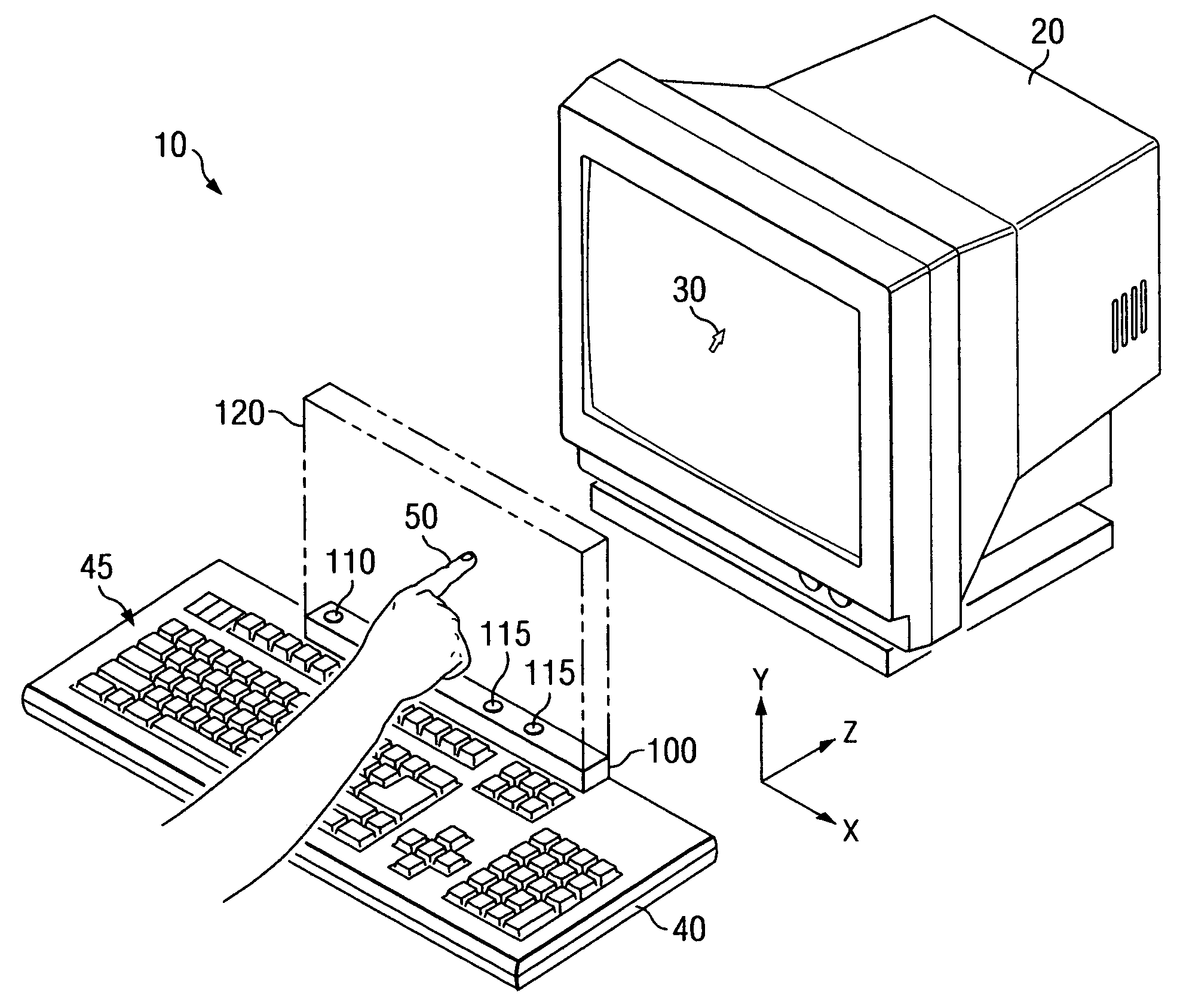
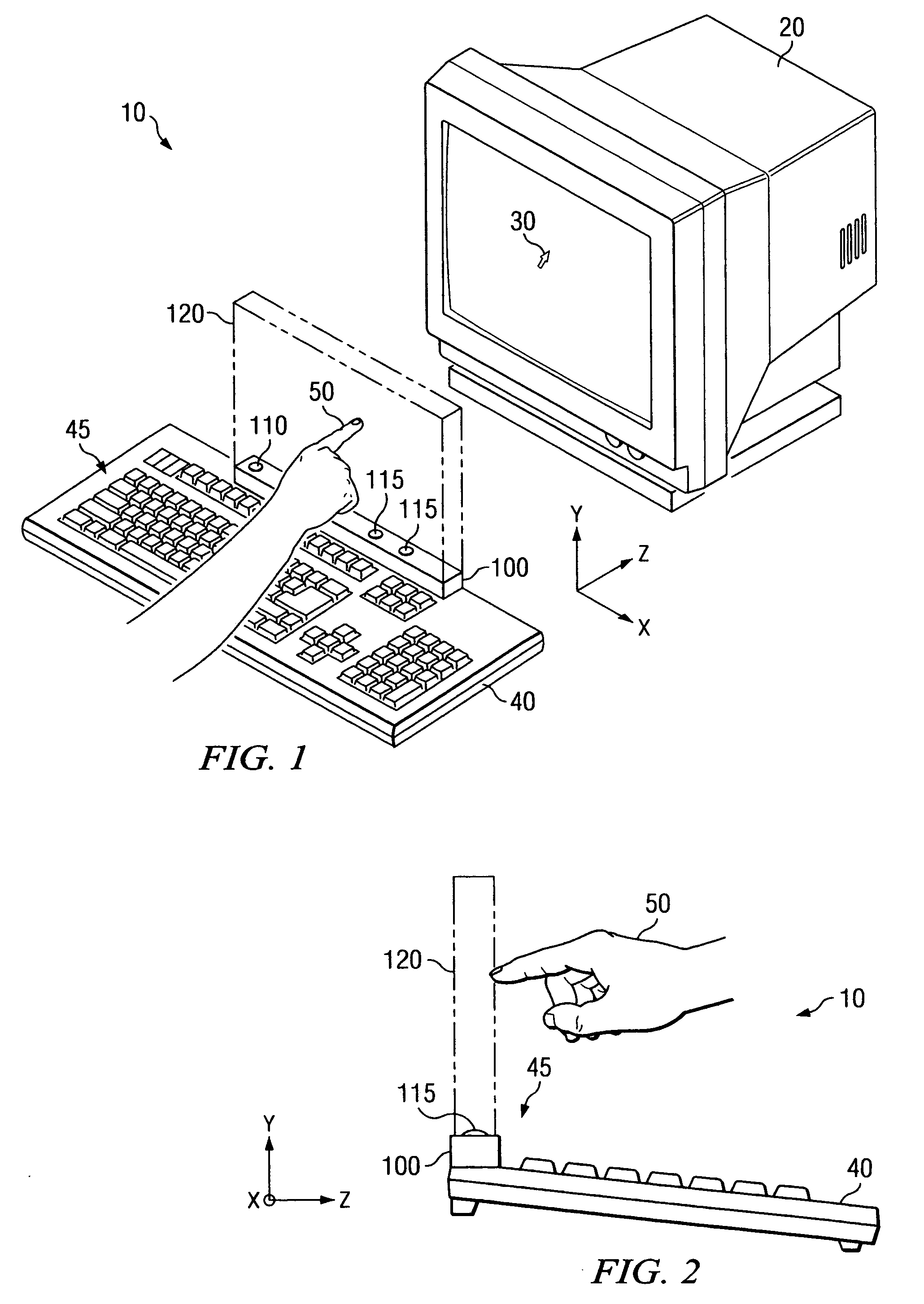
[0018]FIG. 1 is a perspective view of an exemplary electronic device 10 including an ultrasonic virtual mouse 100 for determining the position of a user-controlled object 50, such as a finger, pen, pointer or other stylus, within a virtual mouse region 120, in accordance with embodiments of the present invention. The electronic device 10 shown in FIG. 1 is a desktop computer. However, in other embodiments, the ultrasonic virtual mouse 100 is implemented in another electronic device. For example, various electronic devices include wireless (cellular) telephones, personal digital assistants (PDAs), laptop computers, notebooks, hand-held video game devices, portable music players or other similar electronic devices.

[0019] The ultrasonic virtual mouse 100 is shown located on the top surface 45 of a keyboard 40 of the electronic device 10. However, it other embodiments, the ultrasonic virtual mouse 100 is located on a side surface of the keyboard 40 or is a stand-alone device. In embodi...


PUM


Abstract

An ultrasonic device determines a position of a user-controlled object within a virtual mouse region. The ultrasonic device includes an ultrasonic transmitter, spatially separated ultrasonic receivers and a processor. The ultrasonic transmitter produces an ultrasonic pulse and radiates the ultrasonic pulse into the virtual mouse region. The ultrasonic receivers receive a reflected ultrasonic pulse reflected from the user-controlled object within the virtual mouse region and produce respective reflected ultrasonic signals in response thereto. The processor determines the position of the user-controlled object within the virtual mouse region based on the reflected ultrasonic signals, and generates a position signal indicative of the position.

Description

BACKGROUND OF THE INVENTION [0001] Traditional cursor control devices for controlling movement of a cursor to point to and / or select items or functions on a display of a desktop or laptop computer include arrow keys, function keys, mice, track balls, joysticks, j-keys, touchpads and other similar devices. Of these, the most popular cursor control device is the mouse. Essentially, a mouse operates using a mechanical, optomechanical or optical mechanism to translate motion of the mouse across a workspace into electrical signals that produce motion of the cursor on the display. The mouse is typically located on a mouse pad or other surface adjacent a keyboard, and operation of the mouse requires the user to move his or her hand from the keyboard to the mouse. [0002] Although the mouse is an adequate cursor control device for many applications, in environments in which the mouse must operate in a limited workspace, users are generally dissatisfied with the maneuverability, and therefore...

Claims


Application Information

Patent Timeline
IPC IPC(8): G09G5/08
CPCG06F3/043
Inventor SCHROEDER, DALE W.NISHIMURA, KEN A.WENSTRAND, JOHN STEWART
Owner AVAGO TECH ECBU IP (SINGAPORE) PTE LTD
Why Eureka
Try Eureka