Pipe inspection systems and methods

a technology of ultrasonic pipe inspection and inspection system, applied in the direction of instruments, specific gravity measurement, processing detected response signals, etc., can solve the problems of ct fracturing, affecting the performance of the system, and affecting the quality of the pip

Inactive Publication Date: 2004-08-31
COILED TUBING ENG SERVICES
View PDF24 Cites 52 Cited by
  • Summary
  • Abstract
  • Description
  • Claims
  • Application Information

AI Technical Summary

Problems solved by technology

Nuclear measurements require a nuclear source, which makes them impractical for many applications.
Systems using electromagnetic measurements have been used for diameter and ovality measurement, and for finding anomalies, flaws and defects in the pipe, such as cracks, but often such systems have not proven accurate for measuring the wall thickness in one localized area of the pipe.
Some services, such as CT fracturing, tend to erode the inner surface of the CT in some areas.
Also, the CT wall may be worn when used in wells with chrome tubulars.
Often the coupling fluid treatment and sealing system makes UT systems such as the one described in U.S. Pat. No. 5,303,592 difficult to use in some applications.
These wheel-probe based UT systems may be too complex for some pipe inspection applications.

Method used


Image

  • Pipe inspection systems and methods
  • Pipe inspection systems and methods
  • Pipe inspection systems and methods

Examples


Embodiment Construction

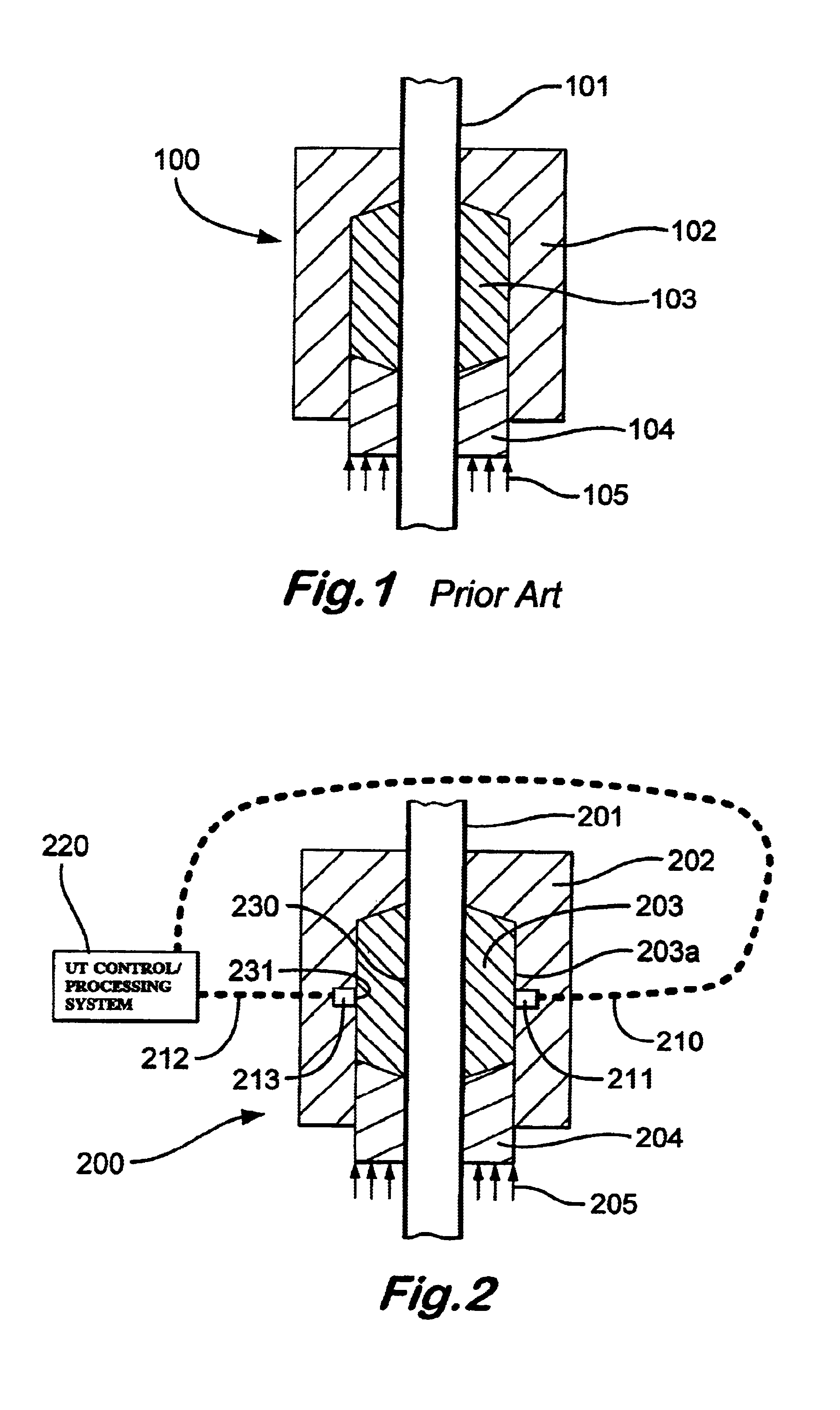
FIG. 1 shows a prior art stripper packer system 100. Pipe 101 (which may be any tubular or CT), passes through the stripper packer. The stripper packer has an outer housing 102, a packer element 103, and a movable piston 104. Pressure or force 105 is applied to the piston, causing it to compress the packer element against the pipe 101.

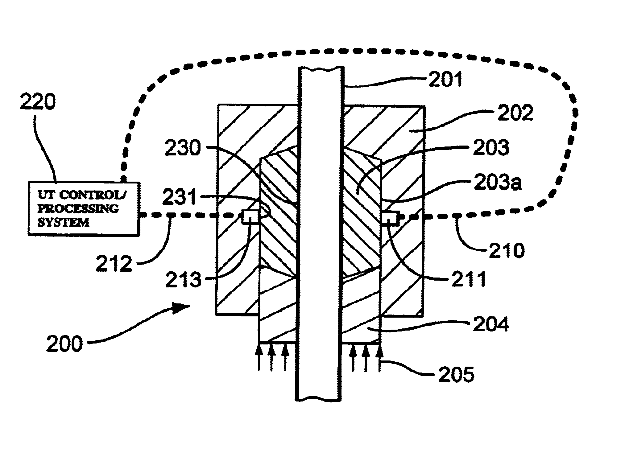
FIG. 2 shows a system 200 according to the present invention with UT pipe inspection capabilities. A generally cylindrical hollow pipe 201 passes through a housing 202 with an elastomeric element 203 in a cavity 203a. The element 203 surrounds the pipe and is compressed by force or pressure 205 on a piston 204. UT probes 211 and 213 are affixed to or embedded in a housing 202. Electrical wires 210 and 212 from the probes 211 and 213, respectively, pass out of the housing 202 and to a UT control / processing system 220 (which may also display results). When the element 203 is subjected to a compressing force or pressure 205 (in a direction generally in th...


PUM

PropertyMeasurementUnit
thicknessaaaaaaaaaa
compressing forceaaaaaaaaaa
elastomericaaaaaaaaaa

Abstract

Systems and methods for ultrasonically inspecting pipe, the pipe having a longitudinal axis, the methods in certain aspects including compressing with a compressing force an elastomeric element between an ultrasonic probe of an ultrasonic pipe inspection system and a pipe to be inspected; and, in certain aspects, the systems and methods including placing a coupling between the elastomeric element and the pipe, wherein the elastomeric element surrounds the pipe; and, in certain aspects, a system for ultrasonically inspecting pipe, the system with a housing, a packer element in the housing with an opening through which a pipe to be inspected is passable, and at least one ultrasonic probe in or on the housing useful in conjunction with an ultrasonic apparatus for inspecting pipe.

Description

1. Field of the InventionThe present invention is directed to ultrasonic pipe inspection systems and methods.2. Description of Related ArtMany systems have been developed to inspect pipe. A variety of these systems measure the diameter, ovality, and wall thickness. They also look for flaws in the pipe such as cracks and pits. Some versions of these systems have been adapted for inspecting coiled tubing (CT). These systems can be categorized in three major types: nuclear--some type of radiation such as gamma rays are passed through the pipe and the reflections are measured; electromagnetic--magnetic flux is passed through the pipe and the flux flow or flux leakage is measured; and ultrasonic (UT)--ultrasonic sound is passed through the pipe and the reflections are measured. Nuclear measurements require a nuclear source, which makes them impractical for many applications.Systems using electromagnetic measurements have been used for diameter and ovality measurement, and for finding ano...

Claims


Application Information

Patent Timeline
Patent Type & Authority Patents(United States)
IPC IPC(8): G01N29/44G01N29/22G01N29/38G01N29/28G01N29/36
CPCG01N29/225G01N29/28G01N29/38G01N29/44G01N2291/0226G01N2291/02827G01N2291/02854G01N2291/0421G01N2291/0422G01N2291/044G01N2291/048G01N2291/2634
Inventor LINARES, LIONEL S.NEWMAN, KENNETH R.
Owner COILED TUBING ENG SERVICES
Why Eureka
Try Eureka