Connecting device for a plug-and-socket connection containing two connectors

a technology of connecting device and socket, which is applied in the direction of coupling device connection, incorrect coupling prevention, electrical apparatus, etc., can solve the problems of manual insertion of connectors, bending of relatively thin centering pins, and obligatory mechanical play between pins

Inactive Publication Date: 2007-04-19
SIRONA DENTAL SYSTEMS
View PDF5 Cites 11 Cited by
  • Summary
  • Abstract
  • Description
  • Claims
  • Application Information

AI Technical Summary

Benefits of technology

[0012] This assures that the two connectors are in alignment along their center axes when the second part and the plate resting thereon are pivoted toward the first part, and that the two connectors are prevented from jamming or being permanently deformed during the connecting operation.
[0014] The connectors are advantageously electrical contacts. It is thus possible to achieve electrical plug-and-socket connections that are also suitable for everyday use with the advantage that known problems such as loose contacts caused by permanent deformations are avoided.
[0015] According to an advantageous development, the connectors are configured as pipe sections for conducting gases or liquids. In this manner a secure sliding socket joint is possible between, say, two pipe sections with the advantage that the two pipe sections are in exact alignment, thus achieving the required seal relative to the environment. Another advantage is that the mechanics of the connecting device of the invention define an insertion distance along which the two pipe sections are connected together. This allows for reproducible conditions and thus the realization of a secure plug-and-socket connection, as is not the case with manual connecting.
[0018] The second part is also advantageously secured against falling out in all intermediate positions between the release position and the closed position in that the lower semicircle of the axle pin is recessed such that the upper semicircle can be inserted into the axle bearing along a longitudinal groove and hooked therein due to the weight of the second part, which is pushed downwardly to produce a form fit with the upper part of the axle bearing being in the form of a segment of a circle. The advantage of this form fit is that no other mechanical means are necessary for locking other than the two parts of the connecting device and that locking is accomplished as soon as the two parts are joined together, and no further expenditure of time is required.
[0020] A rotation stop is advantageously provided for the action of pivoting the plate toward the first part, said stop being configured such that the plate is only capable of being pivoted through an angle a in the release position. In this manner, the maximum angle a for pivoting can be defined such that the necessary insertion distance is achieved precisely. Unnecessary pivoting past the angle a is thus prevented. The angle of the first part to the second part must therefore be at least as large as the angle a when the upper semicircle of the axle pin is inserted into the axle bearing along the longitudinal groove, in order to prevent the axle pin from falling out.
[0022] Locking means are advantageously provided, by means of which the second part is preventing from pivoting back when the closed position is reached. This ensures that the two parts are immovably fixed to each other and that the two connectors remain closely connected.

Problems solved by technology

This suffers from the drawback that an obligatory mechanical play must exist between the pins and the plugs.
Furthermore, with use, it is possible that the relatively thin centering pins may be bent.
A disadvantage of plug-and-socket connections disclosed in the prior art is that the connectors must be plugged together manually.
If the connectors are not in alignment, they jam and become permanently deformed.
An additional disadvantage is that jamming can also occur during manual disengagement of the plug-and-socket connection.

Method used


Image

  • Connecting device for a plug-and-socket connection containing two connectors
  • Connecting device for a plug-and-socket connection containing two connectors
  • Connecting device for a plug-and-socket connection containing two connectors

Examples


Embodiment Construction

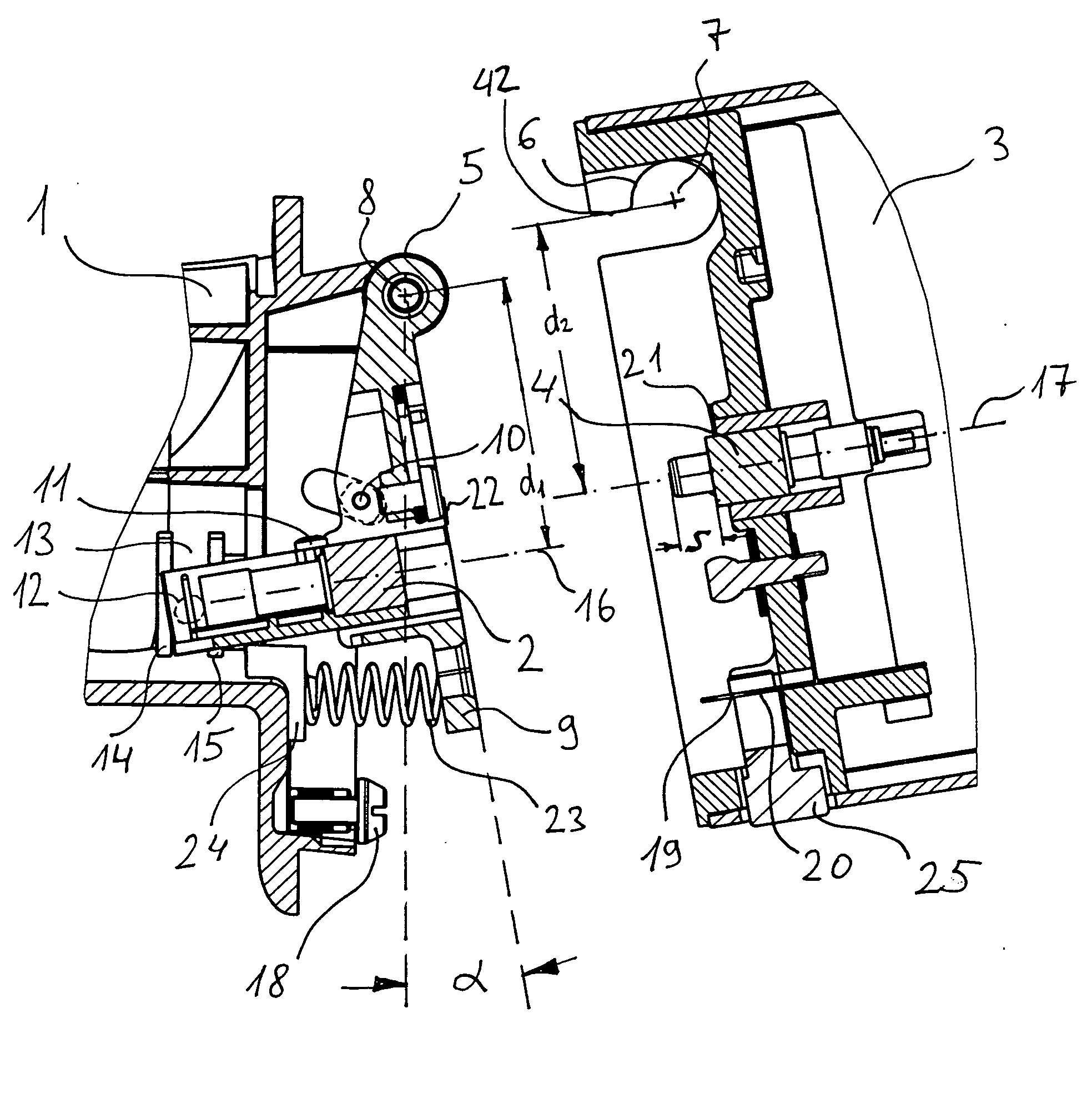
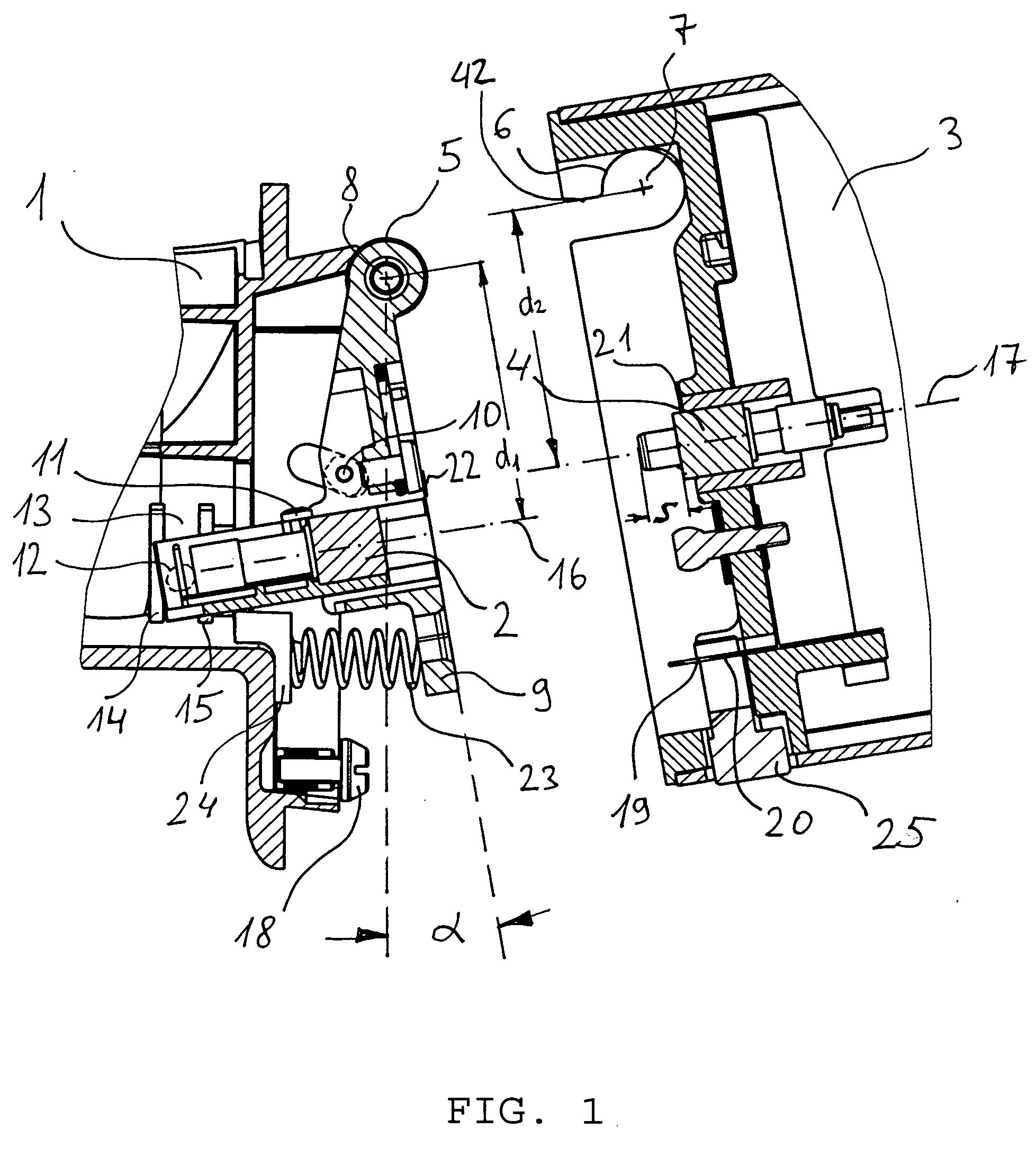
[0035] The connecting device represented in FIG. 1 has a first part 1 with a first connector 2 and a second part 3 with a second connector 4. The first part 1 is equipped with an axle pin 5 and the second part 3 has an axle bearing 6 for said axle pin 5. The second part 3 is capable of being pivoted about an axis of rotation 7 defined by the axle bearing 6, which axis coincides with the center axis 8 of the axle pin 5 in the plugged state of the connecting device. The axle pin 5 is cylindrically configured and in the plugged state it is located inside the axle bearing 6.

[0036] Furthermore, the first part 1 comprises a plate 9 that is likewise capable of being pivoted about the center axis 8, wherein a rotation stop 10 prevents pivoting beyond an angle a. Pivoting and thus the effort expended by a user in fixing the second part 3 onto the first part 1 is thus restricted to the absolutely necessary amount.

[0037] The angle a is such that a maximum insertion distance is created as the...


PUM


Abstract

The invention relates to a connecting device for a plug-and-socket connection containing two connectors, comprising a first part (1) with a first connector (2) and a second part (3) with a second connector (4). The first part (1) is equipped with an axle pin (5), and the second part (3) is equipped an axle bearing (6) for said axle pin (5), wherein said second part (3) is capable of being pivoted from a release position to a closed position about an axis of rotation (7) defined by the axle bearing (6), wherein the distance d1 of the center axis (16) of the first connector (2) from the axis of rotation (8) is equal to the distance d2 of the center axis (17) of the second connector (4) from said axis of rotation (8). In order to avoid jamming and permanent deformation during the connecting operation, the first connector (2) will always be in alignment with the second connector (4) during the pivoting operation. The connecting device of the invention is well-suited for the simple realization of plug-and-socket connections in the clinical field, in which a secure plug-and-socket connection is of paramount importance.

Description

TECHNICAL FIELD [0001] The invention relates to a connecting device for a plug-and-socket connection containing two connectors, comprising a first part with a first connector and a second part with a second connector and further relates to the problem of expediently producing a secure plug-and-socket connection without the connectors jamming against each other and becoming permanently deformed. DESCRIPTION OF THE RELATED ART [0002] Several connecting devices for plug-and-socket connections are disclosed in the prior art. [0003] DE 295 07 560 U1 discloses a dental treatment unit with a holder for a portable accessory device for a dental treatment center. A combined hook-and-plug system is disclosed in an exemplary embodiment. The accessory device has a bar that is hooked into two hooks on the holder. In a depression, the holder has a tiltably-mounted terminal block, which, on the one hand, has sockets for a mechanical adjustment of the accessory device by means of centering pins and,...

Claims


Application Information

Patent Timeline
Patent Type & Authority Applications(United States)
IPC IPC(8): H01R13/627
CPCH01R13/635H01R35/04
Inventor HUCH, JOCHENENGERT, REINHARD
Owner SIRONA DENTAL SYSTEMS
Why Eureka
Try Eureka