Boring machine

a micro-tunnelling machine and machine body technology, applied in cutting machines, artificial islands, underwater structures, etc., can solve the problems of not being widely used, expensive laser guided micro-tunnelling machines, and excavation may be needed to investigate, so as to simplify and cheapen the construction of machines

Inactive Publication Date: 2007-04-26
DAVIES RODNEY JOHN
View PDF30 Cites 32 Cited by
  • Summary
  • Abstract
  • Description
  • Claims
  • Application Information

AI Technical Summary

Benefits of technology

[0009] Means to convey the image may be a video camera. The target may be a surface against which the laser can be seen in contrast. The target may have a series of concentric rings, cross hairs or equivalent markings to help the operator to centre the direction of the boring bit.
[0013] Control of waterflow to the hydraulics may be by solenoid operated valves. This is convenient if the hydraulic rams and the valves are grouped together in the boring head making it necessary to supply the head with a water feed conduit, low voltage electrical leads and a large bore slurry removal conduit. The moving parts may therefore be reduced to the drive shaft, the associated rams and the boring bit. This layout simplifies and cheapens the construction of the machine. It is not onerous to watch the monitor and correct the direction of the bore intermittently. Once aligned, the bore tends to maintain course unless changes in the subsoil occur. The machine's static base is installed in the pit and its radial direction, ie. NSEW, is selected and thereafter the frame is locked in position. The sliding frame assumes the direction of the static base. The direction of the thrust imposed on the boring head is unchanged during the addition to the string of the add-on drive sections.

Problems solved by technology

If an obstruction is encountered, an excavation may be needed to investigate.
The use of laser technology by drainers is well established, but laser guided micro-tunnelling machines are expensive and not widely used.
Trials and contract boring show that if the electronic components of the device fail, they tend to do so in locations where service and repair is slow or unavailable.
It has also been found that when the strata are uniform, surprisingly infrequent corrections are required in practice, but this was only discovered when a non-automatic version was constructed and tested.

Method used


Image

  • Boring machine
  • Boring machine
  • Boring machine

Examples


Embodiment Construction

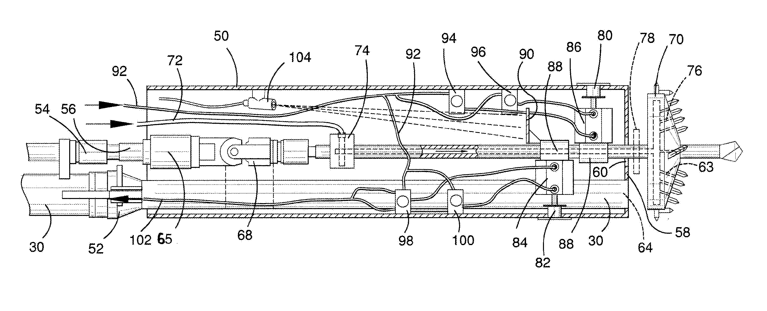
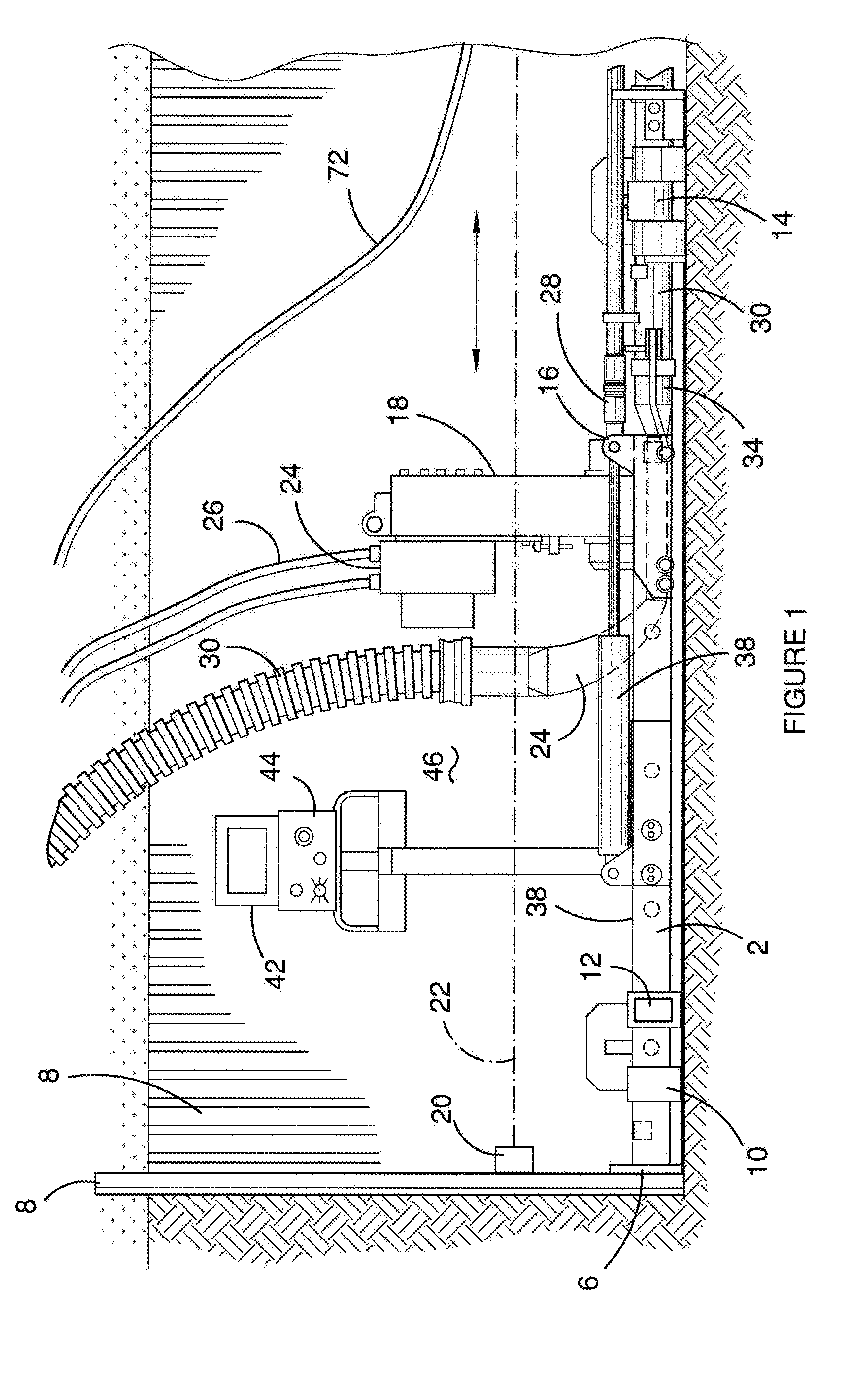
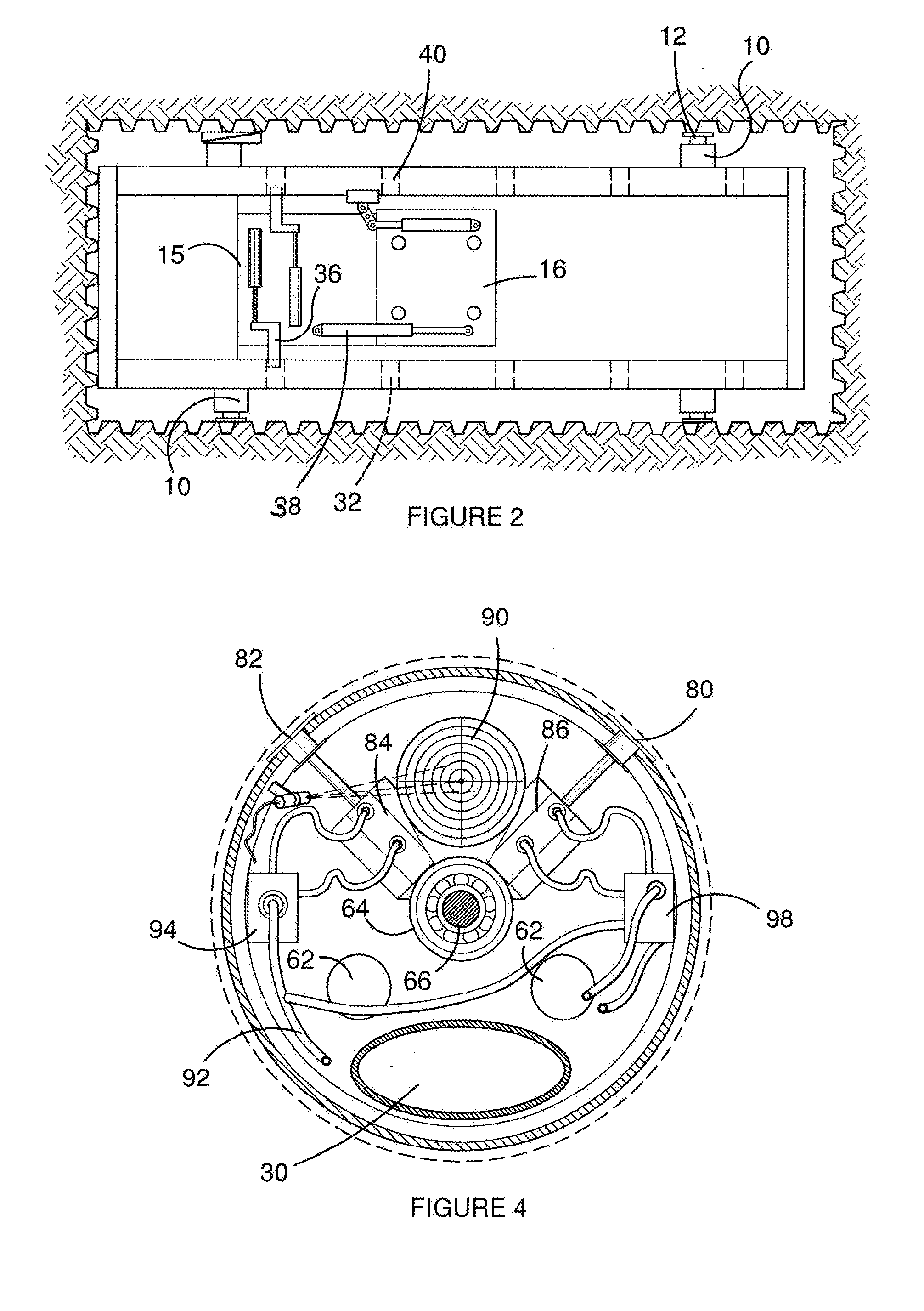
[0021] Referring now to the drawings, once the main excavation and the target excavation have been made the direction and depth of the bore is established by drain laying practice. The main excavation pit accommodates the steel rails 2 of the base frame 4. The rails 2 are joined by brace 6 which contacts the steel plate shuttering 8 lining the pit. The base frame has lugs 10 which extend on both sides toward the side of the pit and jacks 12 are inserted to position the frame radially. In addition, the base frame has a ground jack 14 to adjust its inclination. Once installed and adjusted, the rails remain static.

[0022] A sliding frame 16 engages the rails. The sliding direction conforms to the direction of the base frame and therefore is aligned with the bore path. A retractable drilling assembly 18 (FIG. 1) is fixed to the sliding frame 16. A laser generator 20 is mounted on the steel plate 8 just above the base frame 4. The laser beam 22 is adjusted to reach the required point at ...


PUM


Abstract

A micro tunnelling machine has a tunnelling head with a boring bit which is forced in a horizontal direction by a hydraulic thruster. The direction of the head is laser guided. The beam strikes a target in the head and a camera relays an image of the target to an operator located at the tunnel entrance. The operator adjusts the direction by admitting water and draining water from a pair of rams inside the head which move the boring bit up and down or left and right. Water is introduced into the boring bit through the drive shaft of the boring bit. The water forms a slurry which is extracted by a vacuum pipe which enters the slurry as droplets and particles and conducts them away from the tunnelling head.

Description

CROSS REFERENCE TO RELATED APPLICATION [0001] This application is filed as a continuation-in-part of U.S. patent application Ser. No. 10 / 622,710 filed Jul. 18, 2003, the entire disclosure of which is hereby incorporated by reference herein, and claims priority under 35 USC 119 of Australian Provisional Application No. 2002953110 filed Dec. 5, 2002. FIELD OF THE INVENTION [0002] This invention concerns micro-tunnelling machines of type used to bore underground drainage passages. BACKGROUND OF THE INVENTION [0003] Infill housing frequently requires the provision of services which cross boundaries and which must be precisely located. When the drainage is one of the services, the fall or incline must be incorporated into the final selected direction. Additionally, where line of sight is available to find the radial angle from the bore entrance to the target site, optical instruments provide accuracy. If an obstruction is encountered, an excavation may be needed to investigate. Alternati...

Claims


Application Information

Patent Timeline
Patent Type & Authority Applications(United States)
IPC IPC(8): E21B44/00E21B7/04E21B7/08E21D9/00E21D9/06
CPCE21B7/046E21D9/004E21D9/0628E21D9/093
Inventor DAVIES, RODNEY JOHN
Owner DAVIES RODNEY JOHN
Why Eureka
Try Eureka