Wheeled skate

a wheeled skate and skate technology, applied in the field of wheeled skates, can solve the problems of inability to selectively remove the upper, the wheeled skate is often relatively large, and the upper is normally unsuitable for standing alone and serving as a conventional footwear,

Inactive Publication Date: 2007-04-26
LYDEN ROBERT M
View PDF99 Cites 21 Cited by
  • Summary
  • Abstract
  • Description
  • Claims
  • Application Information

AI Technical Summary

Benefits of technology

[0026] The present invention teaches an apparatus and method for securing an article of footwear that is suitable for walking, running, or bicycling to a wheeled skate. Further, the present invention teaches brake devices which can facilitate use of toe stop, toe drag, heel drag, snow-plow, and hockey-stop braking maneuvers. The wheeled skates and brakes are configured to enable a skater to retain balance, control and maneuverability even when engaged in hard braking. In addition, the present invention teaches a wheeled skate which can be propelled with the use of linear or side stroke skating techniques.
[0039] A wheeled skate can comprise a chassis, and an article of footwear can comprise an anterior side, a posterior side, a medial side, a lateral side, a forefoot portion, and a rearfoot portion. The wheeled skate and article of footwear can comprise means for removably securing the forefoot portion of the article of footwear to the wheeled skate comprising a footwear portion of locking mechanism assembly secured to the article of footwear, and the chassis of the wheeled skate comprising a compatible skate portion of locking mechanism assembly. The footwear portion of locking mechanism assembly and the skate portion of locking mechanism assembly are capable of being removably secured in functional relation by inserting and rotating compatible portions thereof. The wheeled skate can further include means for removably securing the rearfoot of the article of footwear to the chassis of the wheeled skate. The means for removably securing the rearfoot of the article of footwear to the chassis of the wheeled skate can include the use of a rearfoot retainer flange encompassing a portion of the medial, lateral, and posterior sides of the article of footwear. When the forefoot of the article of footwear is secured in functional relation to the chassis of the wheeled skate and the rearfoot is inserted in functional relation to the rearfoot retainer flange, the rearfoot of the article of footwear can then be further secured by fastening means to the rearfoot retainer flange. The footwear portion of locking mechanism assembly can comprise a bicycle cleat portion of bicycle cleat locking apparatus, whereby the article of footwear can be removably secured in functional relation to a bicycle pedal including a compatible pedal portion of bicycle cleat locking apparatus, and alternatively, to the chassis of the wheeled skate comprising the skate portion of locking mechanism assembly.
[0058] A method of removably securing an article of footwear to a wheeled skate, the wheeled skate comprising a longitudinal axis, a skate portion of locking mechanism assembly having a first center of rotation, and a rearfoot retainer flange. The article of footwear comprises an upper for receiving and securing the foot of a wearer. The article of footwear having an anterior side, a posterior side, a superior side, an inferior side, a medial side, and a lateral side, a forefoot, and a rearfoot, the forefoot extending greater than one half of the length of the article of footwear when measured from the posterior side, and the rearfoot extending between the posterior side and one half of the length of the article of footwear. The article of footwear further includes a footwear portion of locking mechanism assembly having a second center of rotation secured to the inferior side of the forefoot. Accordingly, when the wearer dons the article of footwear and places the second center of rotation of the footwear portion of locking mechanism assembly in alignment with the first center of rotation of the skate portion of locking mechanism assembly when the rearfoot of the article of footwear is rotated laterally with respect to the longitudinal axis of the wheeled skate in the range between 0-40 degrees, the footwear portion of locking mechanism assembly and the skate portion of locking mechanism assembly are each positioned for mechanical engagement. The wearer can then sufficiently elevate the rearfoot of the article of footwear to clear the lateral side of the rearfoot retainer flange while rotating the rearfoot of the article of footwear medially. The wearer can then place the article of footwear in substantial alignment with the longitudinal axis of the wheeled skate thereby mechanically engaging and locking the footwear portion of locking mechanism assembly and the skate portion of locking mechanism assembly causing the forefoot of the article of footwear to be secured to the wheeled skate. The wearer can then removably secure the rearfoot of the article of footwear to the wheeled skate by lowering the rearfoot within the confines of the rearfoot retainer flange, the rearfoot retainer flange then encompassing the rearfoot of the article of footwear on a portion of the medial, posterior, and lateral sides. The wearer can then further removably secure the rearfoot of the article of footwear to the wheeled skate using fastening means.

Problems solved by technology

A few modern wheeled skate uppers can be removed, but most are not intended to be selectively removable.
If and when removed from a wheeled skate, these uppers are normally unsuitable to stand alone and serve as a conventional article of footwear.
These types of wheeled skates are often relatively large, awkward, heavy, and expensive.
They generally do not breathe well, and as result can be hot and uncomfortable.
Wheeled skates of this kind are not easy to transport, and take up considerable space when packing and traveling.
However, these attempts to re-introduce a more conventional and selectively removable shoe upper have not met with great commercial success.
However, the present inventor believes that there are other reasons for the commercial failure of these initiatives.
This is one of the bottlenecks or problems which has stifled the industry.
The hockey skate is faster, but it is both less maneuverable and less capable of providing high quality skating relative to the figure skate.
Many of the maneuvers commonly performed by figure skaters are simply not possible on a hockey skate.
The relatively high elevation of conventional in-line skates makes skating more difficult for the general public, and likely contributes to many of the falls and injuries which are experienced during in-line skating.
In fact, the speeds provided by current in-line hockey and speed skates can be unmanageable as concerns safety and braking, in particular, given the presence of hilly terrain or a traffic filled environment.
Today, most wheeled skates are simply too fast to effectively control given the height at which the foot is elevated, the hazards present in an urban or suburban environment, and the lack of truly effective braking systems.
The adoption of the hockey skate geometry and model, and focus on attaining high speeds has limited the potential of wheeled skates to meet other criteria with respect to skating, such as the consumer's desire for a non-impact form of aerobic exercise and safety.
Both of these side stroke styles place considerable loads upon the ankle, knee, hip, and lower back of skaters.
In truth, the side stroke skating style is more taxing on the anatomy, and more likely to result in injury than the relatively linear stroke technique used in figure skating.
The side stroke skating style is also harder to learn and to manage than the linear stroke technique.
The side stroke skating style also requires considerable space in order to execute.
On a sidewalk or street, the presence of cars and pedestrians and the danger of collision renders the side stroke style somewhat less safe or manageable.
This technique requires numerous quick side strokes in order to gain elevation, and is both physically taxing and inefficient.
However, there appears to be no teaching with respect to the use of a step-in bicycle cleat system in the wheeled skate prior art.
When speaking of in-line wheeled skates, it is not really possible to introduce rocker in a two-wheeled skate, but such is possible with skates having three or more wheels.
In a quad wheeled skate, that is, in a four wheeled skate in which the wheels are not positioned in-line, it is normally not possible to perform the so-called hockey-stop braking action unless the skating surface is exceptionally smooth, and / or the frictional characteristics of the wheel and skating surface permit.
When braking on a rough surface, the rearmost wheel can then become rapidly abraded.
Most of the existing rear mounted brakes developed for in-line wheeled skates do not develop sufficient braking power to stop a skater moving at speed within a short distance.
Further, these rear mounted brake systems do not generally permit the execution of rapid avoidance maneuvers while braking, that is, the act of braking is achieved at the expense of maneuverability.
These actions are not conducive to maintaining balance when stopping suddenly.
Unfortunately, these actions are generally inconsistent with the posture and movements required to successfully actuate many of the rear positioned brake systems that are presently being used on in-line wheeled skates.
This can undermine an in-line skater's ability to brake, balance, and maintain control and maneuverability during hard braking.
However, this braking maneuver quickly consumes the rear wheel of a skate, as the wheel then effectively doubles as a brake pad.
This maneuver is also more difficult and dangerous to perform on dry land given the relative unevenness of most skating surfaces.
Moreover, if skaters fall on dry land they will not slide as on ice, and unlike relatively smooth ice, an asphalt skating surface can severely cut and abrade.
Further, while in-line wheeled skates can provide advantages in speed and maneuverability for a proficient skater, they are not as stable or forgiving for use by the general public as quad wheeled skates.

Method used


Image

  • Wheeled skate
  • Wheeled skate
  • Wheeled skate

Examples


Embodiment Construction

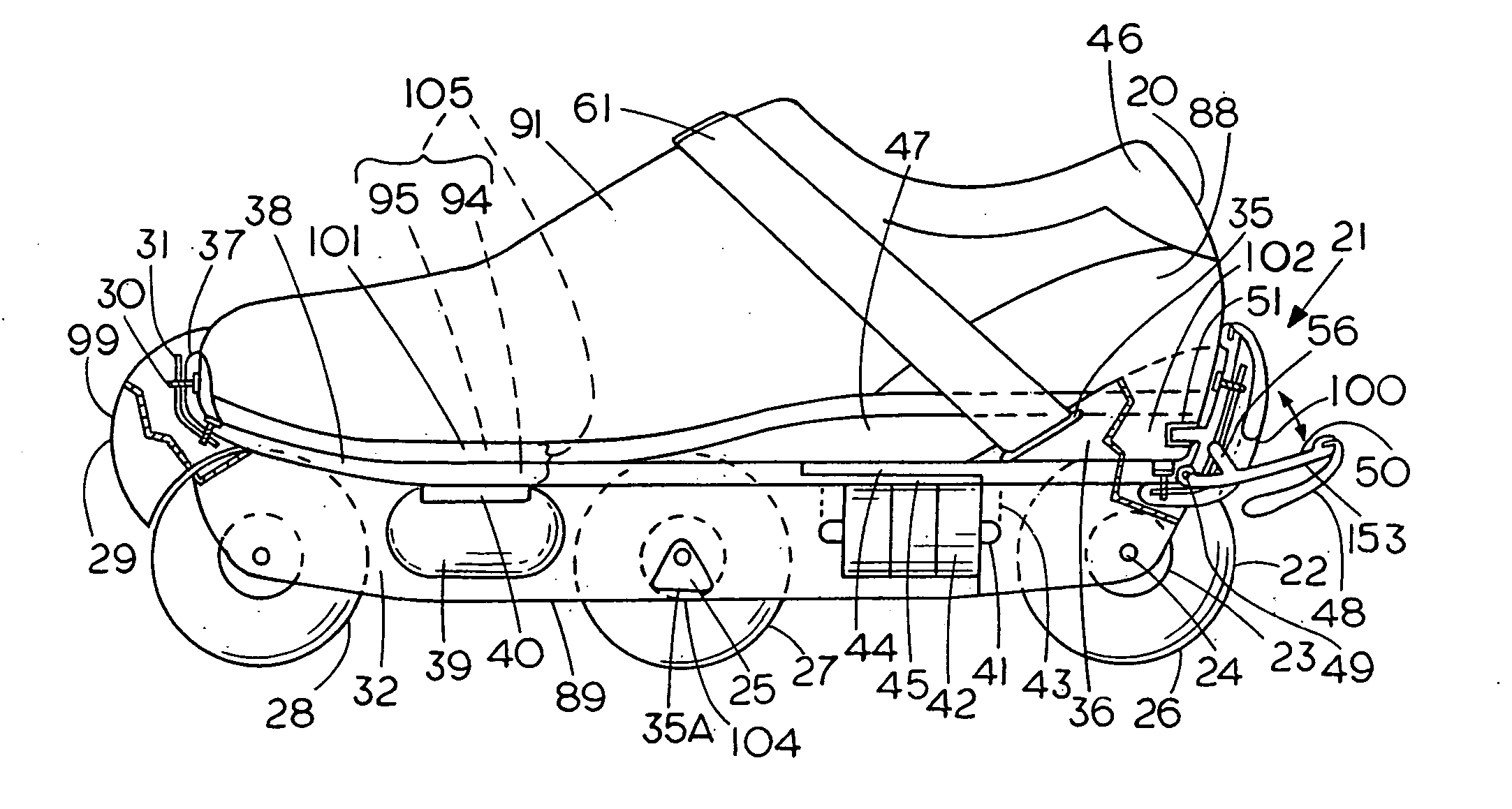
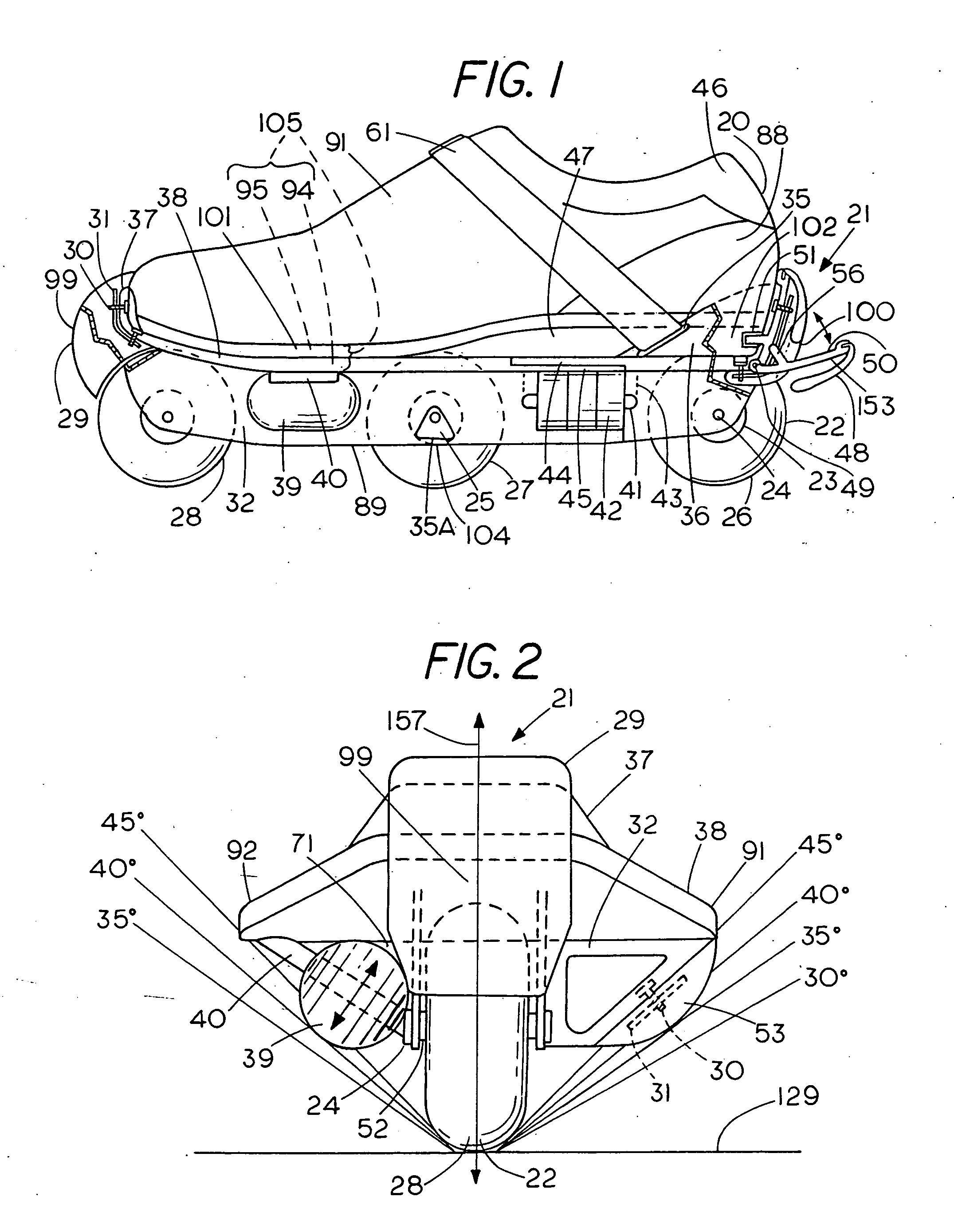
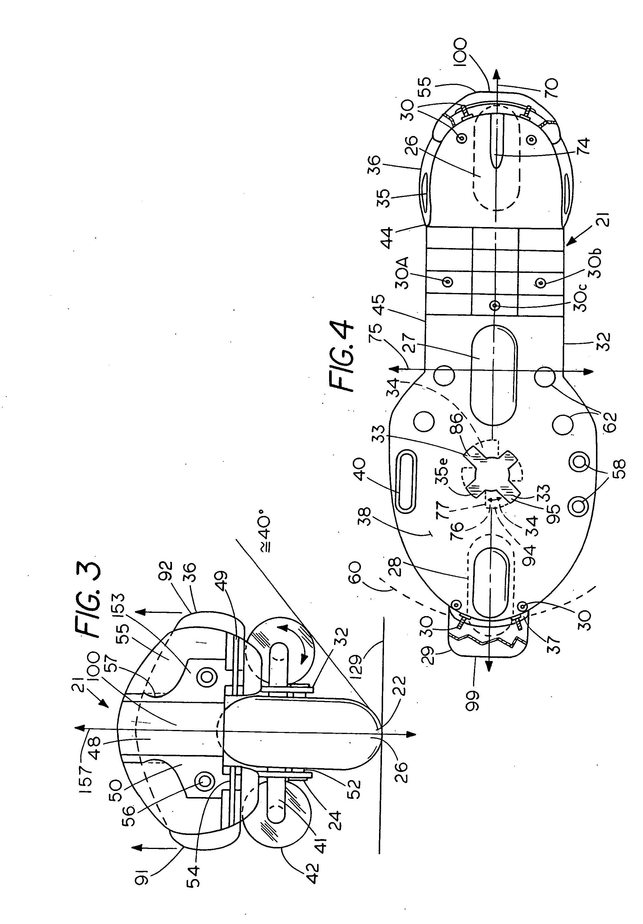
[0115]FIG. 1 is a side view of an article of footwear 20 secured to a wheeled skate 21 having a posterior portion of the chassis 32 and rearfoot retainer flange 36 broken away to show portions of the male rearfoot retainer 153 and the female rearfoot retainer 51. The male rearfoot retainer 153 consisting of a male hinged rearfoot retainer 50 is shown in both an open and closed position with an arrow in order to illustrate operation of the device. In addition, parts of the toe retainer flange 37, chassis 32, and front brake pad 29 are broken away to show retainer 31 and bolts 30. Shown with respect to the wheeled skate 21 are the anterior side 99, medial side 91, posterior side 100, front wheel 28, middle wheel 27, rear wheel 26, axles 24, rocker adjustment device 25, chassis 32, inferior portion of chassis 89, platform 38, footwear portion of locking mechanism assembly 95 and skate portion of locking mechanism assembly 94 which can be mechanically engaged in functional relation to f...


PUM


Abstract

The present invention teaches an apparatus and method for removably securing an article of footwear suitable for walking, running, or bicycling to a wheeled skate. Further, the present invention also teaches a brake device for use with a wheeled skate. In addition, the present invention teaches a wheeled skate including a suspension system that can be propelled with the use of linear or side stroke skating techniques. Moreover, the present invention teaches a quad wheeled skate having advantageous structure and function for recreational skating and aerobic exercise.

Description

CROSS-REFERENCE TO RELATED APPLICATION [0001] The present patent application is a divisional of my pending U.S. patent application Ser. No. 10 / 628,540, filed Jul. 28, 2003, allowed, which in turn is a continuation-in-part of my patent application Ser. No. 09 / 228,206, filed Jan. 11, 1999, now abandoned, and priority for this present application is hereby claimed under 35 U.S.C. §120 based on the above identified U.S. patent applications, and the content of which applications are hereby incorporated by reference.FIELD OF THE INVENTION [0002] The present invention relates generally to wheeled skates, and in particular, to in-line and quad wheeled skates. Further, the present invention relates to the use of locking mechanisms such as step-in bindings with an article of footwear and wheeled skate which can be easily removably attached. In addition, the present invention relates to the use of several brake devices for wheeled skates which can be variously employed by toe drag, snow-plow, ...

Claims


Application Information

Patent Timeline
Patent Type & Authority Applications(United States)
IPC IPC(8): A63C17/02A63C17/06A63C17/14
CPCA63C17/004A63C17/02A63C17/06A63C17/1436A63C2017/0053A63C2201/02A63C2203/42
Inventor LYDEN, ROBERT M.
Owner LYDEN ROBERT M
Why Eureka
Try Eureka