Cable exit for an electrical connector assembly
a technology of coaxial cable connectors and assembly parts, which is applied in the direction of coupling device details, coupling contact members, coupling device connections, etc., can solve the problems of laborious and difficult assembly of cable connectors
- Summary
- Abstract
- Description
- Claims
- Application Information
AI Technical Summary
Problems solved by technology
Method used
Image
Examples
second embodiment
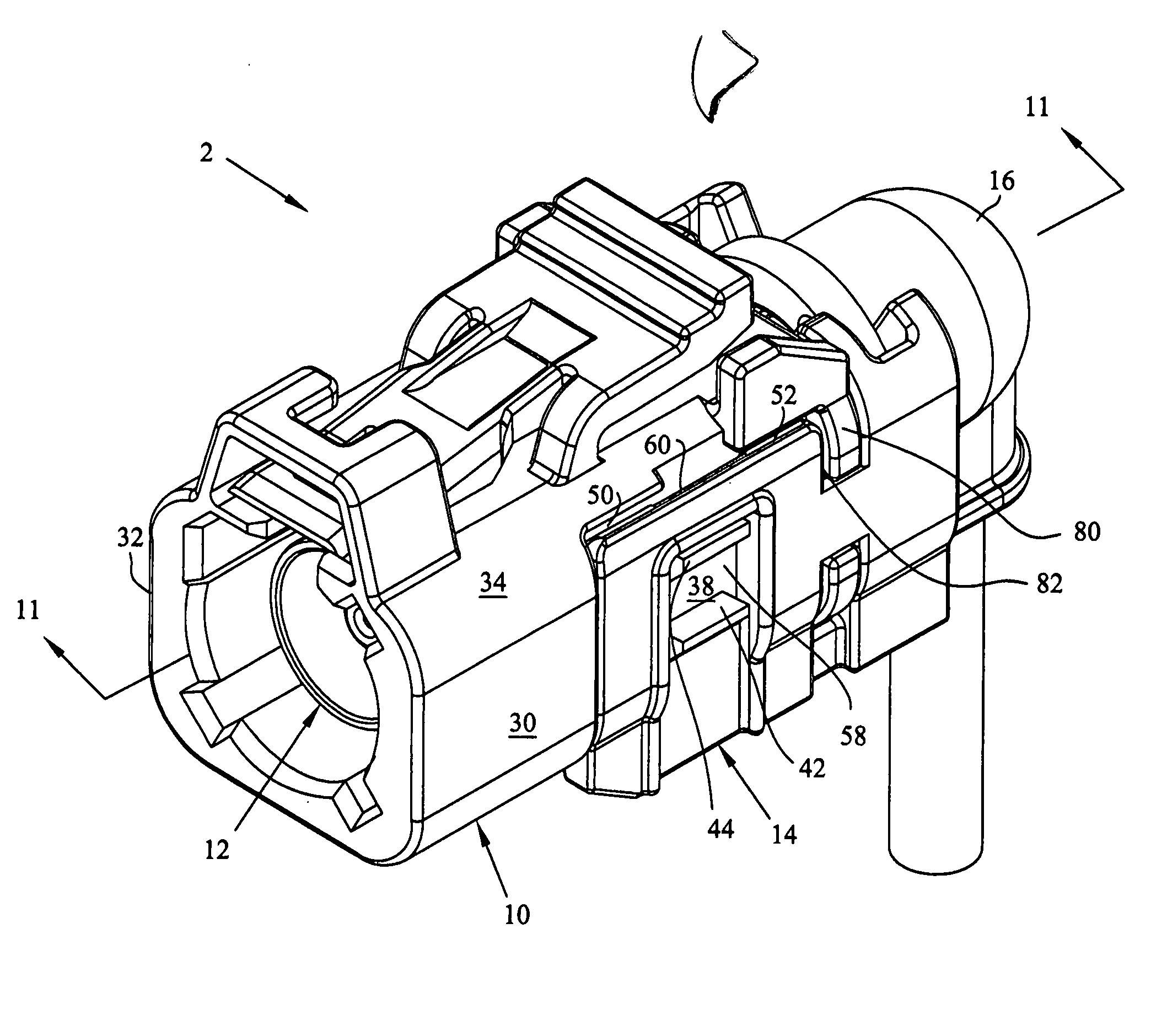
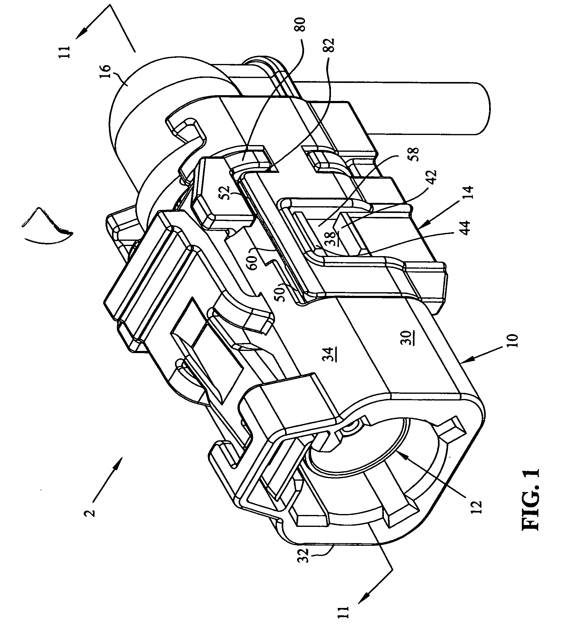
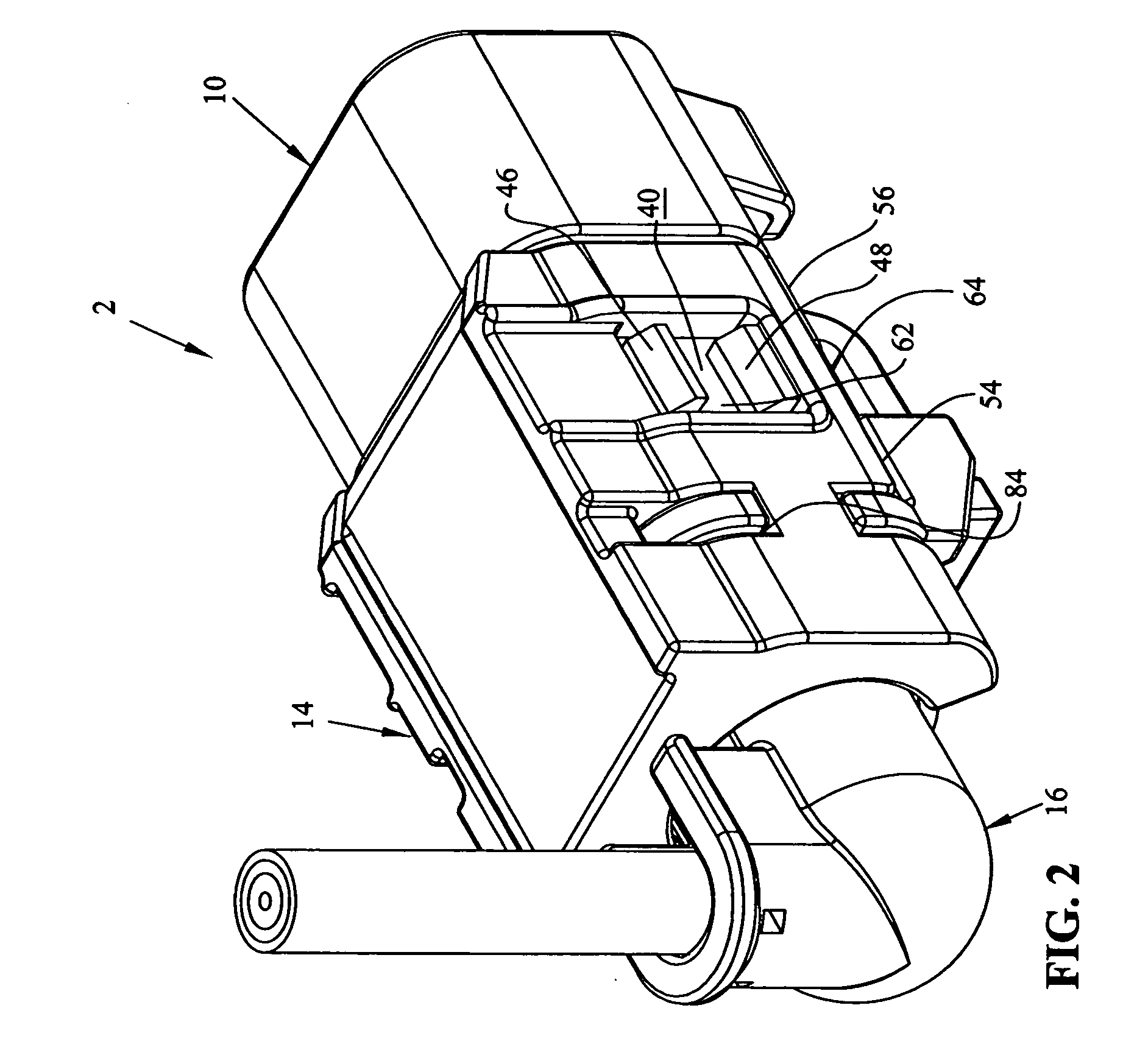
[0045] With reference now to FIGS. 14-20 the coaxial plug assembly is shown at 403. It should be appreciated in this embodiment that the coaxial plug connector 12 as well as the main housing portion 10 are identical to that shown in the embodiment of FIG. 1-13, but that retention housing 414, and cable exit member 416 are modified from corresponding retention housing 14 and cable exit member 16.
[0046] As shown in FIGS. 16 and 17, the retention housing 414 is similar to that shown in FIGS. 7 and 8, and generally includes a lower wall section 400, upstanding wall sections 403 and 404 and terminal locking mechanism 470, but that rear locking plate portion 430 is modified. In particular, channel 432 is not U-shaped but rather is of a circular cross section (FIG. 17) and is defined by inner wall 440 and outer wall 450 with lead in surfaces 454 and 456.
[0047] Meanwhile, as shown in FIGS. 18 and 19, cable exit member 416 includes a dome shaped portion 500 having an exit sleeve 502 which d...
third embodiment
[0049] With reference now to first to FIGS. 21 and 22 the invention is shown at 602. In this embodiment, as in the embodiment of FIG. 14, the main housing portion 10 and coaxial plug contact 12 are identical. However in this embodiment, a new retention housing 614 and cable exit member 616 are provided.
[0050] As best shown in FIGS. 23 and 24, the retention housing 614 will be described. The retention housing 614 includes a lower wall section 600 having upstanding walls 603 and 604 much like the previous embodiment. This housing 614 also includes a terminal locking mechanism 670 upstanding from wall section 600. Retention housing 614 also include a rear locking plate portion at 630 and integrally attached to wall section 600. The locking plate portion 630 has an inner wall portion 640 defining a U-shaped slot 642. Retention housing 614 further includes longitudinally extending locking arms 650 which include diagonally oriented latching surfaces at 652, as best shown in FIG. 24. The l...
fourth embodiment
[0053] With respect now to FIG. 27 and 28, the invention will be described. As in the other three embodiments, the main housing portion 10 and coaxial plug connector 12 are identical. In this embodiment, a modified retention housing 814 and cable exit member 816 are provided. In this embodiment, a modified locking plate 830 is integrally connected to modified ferrule 806 to which cable exit member 816 is locked.
[0054] With respect now to FIGS. 29 and 30 modified ferrule 806 includes a front sleeve 801 having a cable receiving opening at 803. Meanwhile rear locking plate portion 830 is attached to the front sleeve 801 by way of an integral neck 805 to position the locking plate portion 830 in a perpendicular plane to that of front sleeve 801. Locking plate 830 includes apertures 831.
[0055] With respect now to FIGS. 31 and 32, cable exit member 816 includes a generally cyclical barrel portion 817 having integral locking legs 819 extending therefrom. Locking legs 819 include locking l...
PUM
 Abstract
Description
Claims
Application Information
 - Generate Ideas
- Intellectual Property
- Life Sciences
- Materials
- Tech Scout
- Unparalleled Data Quality
- Higher Quality Content
- 60% Fewer Hallucinations
Browse by: Latest US Patents, China's latest patents, Technical Efficacy Thesaurus, Application Domain, Technology Topic, Popular Technical Reports.
© 2025 PatSnap. All rights reserved.Legal|Privacy policy|Modern Slavery Act Transparency Statement|Sitemap|About US| Contact US: help@patsnap.com


