

Method and Apparatus For Spanning Gutter Gaps in Wall Panels
- Summary
- Abstract
- Description
- Claims
- Application Information
AI Technical Summary
Benefits of technology
Problems solved by technology
Method used
Image

Examples
fourth embodiment
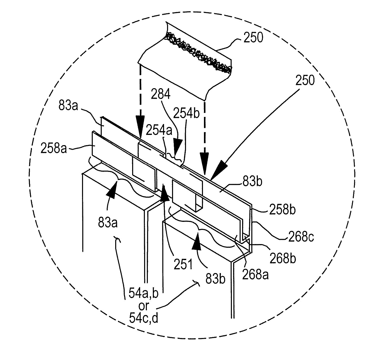
[0042]FIGS. 6A and 6B depict a wall panel attachment system according to the second aspect of the present invention (this second aspect briefly described in the Summary of the Invention section hereinabove). The system uses a flexible sheet interlock 250 (FIG. 6B) to seal inline adjacent perimeter framing members (e.g., perimeter framing members 258a and 258b, which may correspond to one of the pairs of lower perimeter framing members 58a,b or 58c,d of FIGS. 1, 1A and 1C). At the joint or gap 284 between the perimeter framing members 258a and 258b of adjacent wall panels 54a,b (or 54c,d), a flexible sheet interlock 250 inhibits fluid migration along the joint defined by the adjacent ends 254a,b of the adjacent gutter segments (e.g., 83a,b in FIG. 6B) of the perimeter framing members 258a and 258b. The flexible sheet interlock 250 realizes this result by retaining fluids in the adjacent gutter segments 83a,b. Accordingly, the interface (e.g., 260, FIG. 7) between the flexible sheet i...
fifth embodiment
[0059]FIGS. 22-28 depict a fifth embodiment according to the third aspect of the present invention. The wedge-shaped member 306 of the previous embodiment of FIGS. 16-21) is replaced with a screw 404 (FIGS. 23-28, alternatively, screw 404a or 404b in FIG. 22) or other fastener to hold the perimeter framing member 304 (FIGS. 23-28, alternatively, perimeter framing member 304a or 304b in FIG. 22), and the attachment member 308 (FIGS. 23-28, alternatively, attachment member 308a or 308b in FIG. 22) in position on the panel member 54 (FIGS. 23-28, alternatively, panel 54n or 54p in FIG. 22). The fastener passes through the attachment member and perimeter framing member.
[0060] The steps to assemble each panel member assembly 300 of FIG. 22 are illustrated by FIGS. 23-28, with FIG. 23 illustrating the first step, FIG. 24 the second step, FIGS. 25-26 the third step, and FIGS. 27-28 the last step. Additionally, note that FIG. 22 depicts a somewhat different embodiment from that of FIGS. 23-...
PUM
 Abstract
Description
Claims
Application Information