
Power generation systems and method of operating same

a technology of power generation system and wind turbine, which is applied in the field of combined wind turbine and gas turbine system, can solve the problems of reducing the usefulness of wind energy reducing the local marginal pricing of the electricity generated by the wind energy farm, and/or increasing the cycling of the baseload plan

Inactive Publication Date: 2007-05-03
GENERAL ELECTRIC CO
View PDF8 Cites 99 Cited by
  • Summary
  • Abstract
  • Description
  • Claims
  • Application Information

AI Technical Summary

Problems solved by technology

The power output of the wind turbine is limited by either the mechanical load on the turbine blades and / or the mechanical load on the generator or the availability of wind.
More specifically, although wind energy farms provide a clean and renewable source of energy, the power output generated by each wind turbine varies based on the wind, and thus reduces the usefulness of the energy generated by the wind energy farm.
For example, producing wind energy during the night, when demand is relatively low, may result in reduced local marginal pricing of the electricity generated by the wind energy farms and / or increased cycling of the baseload plants. cl BRIEF SUMMARY OF THE INVENTION

Method used


Image

  • Power generation systems and method of operating same
  • Power generation systems and method of operating same
  • Power generation systems and method of operating same

Examples


Embodiment Construction

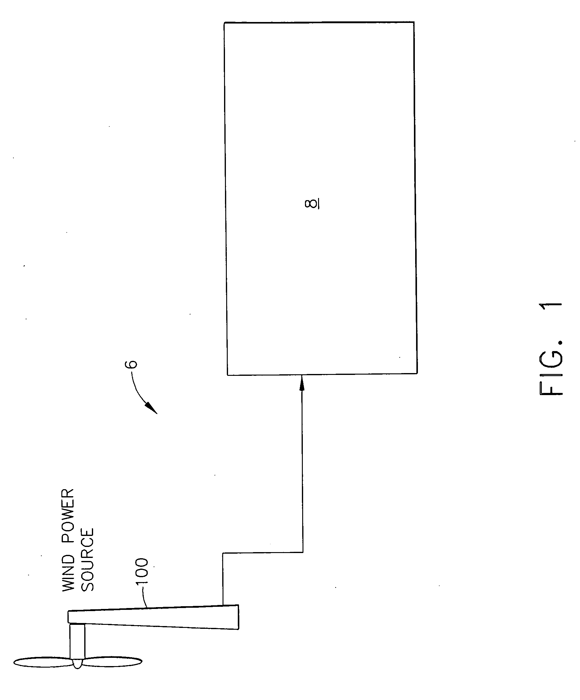
[0015]FIG. 1 is a perspective view of an exemplary power system 6. Power system 6 includes a turbine generator assembly 8 and a wind turbine assembly 100 that is configured to channel compressed air 9 to the gas to the turbine generator assembly 8.

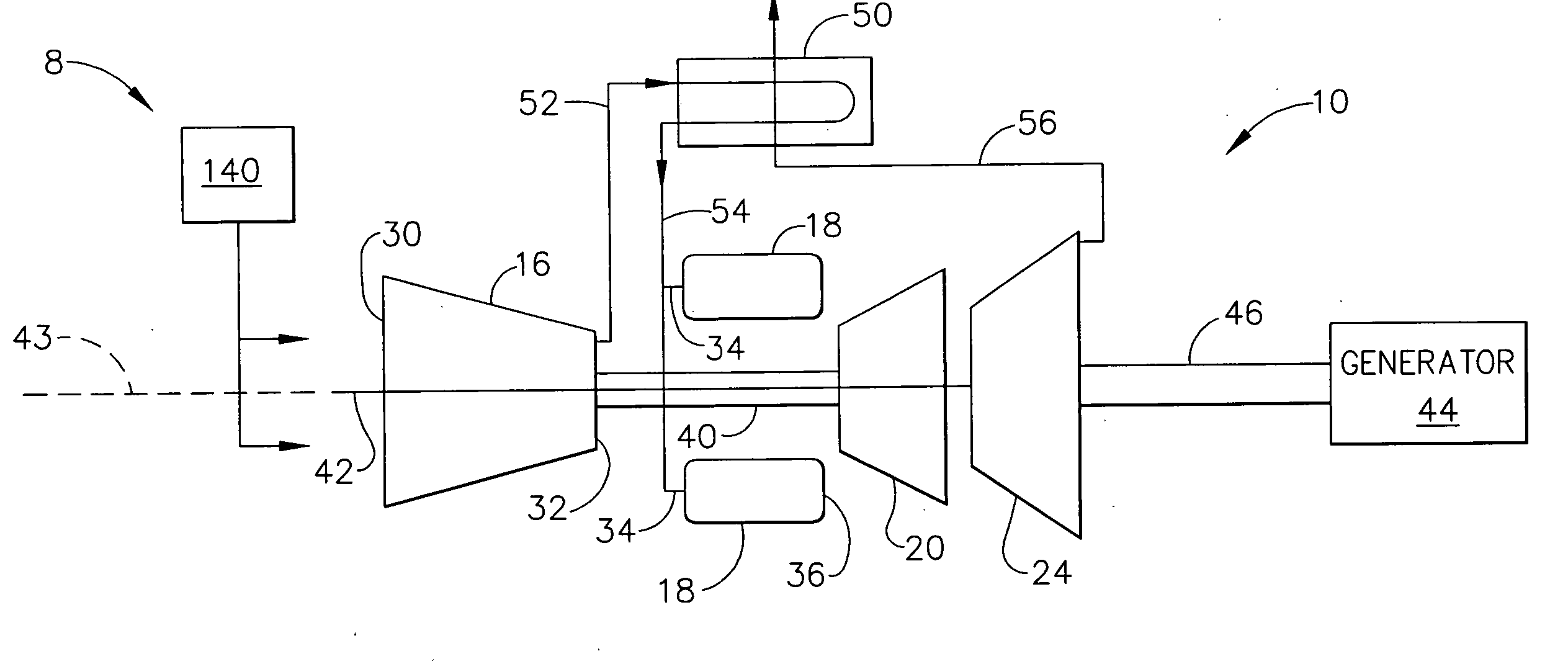
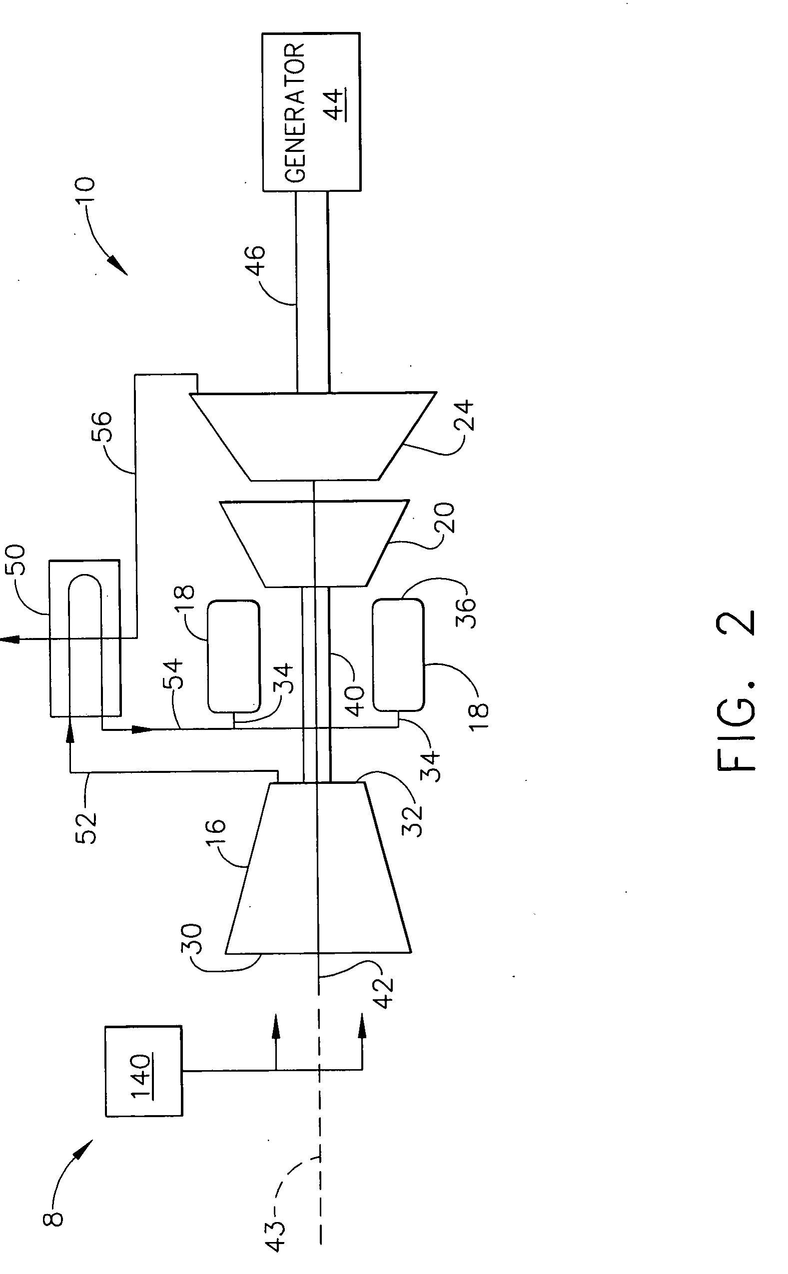
[0016]FIG. 2 is a schematic illustration of an exemplary gas turbine generator assembly 8 that can be used with power system 6. Gas turbine generator assembly 8 includes a gas turbine engine 10 including, in serial flow relationship, a high-pressure compressor 16, a combustor 18, a high-pressure turbine 20, and a low-pressure or power turbine 24. High-pressure compressor 16 has an inlet 30 and an outlet 32. Combustor 18 has an inlet 34 that is substantially coincident with high-pressure compressor outlet 32, and an outlet 36. In one embodiment, combustor 18 is an annular combustor. In another embodiment, combustor 18 is a dry low emissions (DLE) combustor. In a further embodiment, combustor 18 is a can-annular combustor.

[0017] High-press...


PUM


Abstract

A method for operating a power generation system including a wind turbine and a turbine assembly. The method includes operating the wind turbine, storing the energy generated by the wind turbine as compressed air, and channeling the compressed air to the turbine assembly when needed.

Description

BACKGROUND OF THE INVENTION [0001] This invention relates generally to wind turbines, and more specifically to a combined wind turbine and gas turbine system. [0002] In at least one known system, a plurality of wind turbines, commonly referred to as wind energy farms are installed in various geographic locations to facilitate harvesting wind energy when it is available. [0003] The power output of the wind turbine is limited by either the mechanical load on the turbine blades and / or the mechanical load on the generator or the availability of wind. Accordingly, the electrical output of each wind farm varies depending on the various wind conditions and the mechanical load on the wind turbine. More specifically, although wind energy farms provide a clean and renewable source of energy, the power output generated by each wind turbine varies based on the wind, and thus reduces the usefulness of the energy generated by the wind energy farm. For example, producing wind energy during the nig...

Claims


Application Information

Patent Timeline
Patent Type & Authority Applications(United States)
IPC IPC(8): F02C6/00
CPCF02C6/16F03D9/028F05B2220/702Y02E10/72Y02E60/15Y02E70/30F05D2220/72Y02E20/16F03D9/17Y02E60/16F03D9/25F03D9/28
Inventor JOSHI, NARENDRA DIGAMBERRAHM, STEVEN GEORGEBHATNAGAR, ALOK R.
Owner GENERAL ELECTRIC CO
Learn More