Method and device for recovering energy

a technology of energy recovery and energy recovery, which is applied in the field of recovering energy, can solve the problems of poor efficiency, inability to control the entire range of various outside temperatures of any system, and inability to switch from cooling mode to heating mode, etc., and achieves the effect of increasing heat recovery system, large heat recovery, and increasing transfer power

Inactive Publication Date: 2007-05-03
HOMBUCHER HEINZ DIETER
View PDF8 Cites 38 Cited by
  • Summary
  • Abstract
  • Description
  • Claims
  • Application Information

AI Technical Summary

Benefits of technology

[0029] 1. An extremely large heat recovery is achieved. The transfer power WRG achieved with the heat recovery system is increased by the heat pump system configured in the described combination. It is possible to remove more energy from the used air volume flow than is necessary for the heating of the supply air volume flow. The excess energy can optionally be used also for heating service water, e.g., also for heating after the adiabatic humidification of the supply air volume flow.
[0030] In comparison with other heat recovery systems, due to the controllable heat recovery system, the value of the return heat index can exceed 1, while in other, known heat recovery systems, a maximum economical return heat index of 0.8 is achieved.
[0031]ϕ=t⁢ ⁢FOIN⁡(Previously⁢ ⁢Presented)⁢t⁢ ⁢FOOUTt⁢ ⁢FOIN⁡(Previously⁢ ⁢Presented)⁢t⁢ ⁢AUIN
[0040] From this follows for the value of the return heat index: ϕ=24⁢°C-6.8⁢°C24⁢°C-10⁢°C=1.23
[0042] 3. In most circumstances, in the cooling case, the external air AU can be cooled sufficiently that an additional cooling cycle with an additional cooler is not necessary. The cooler in the ventilation device can be eliminated.
[0043] 4. The output received by the supply air ventilator to the shaft becomes smaller, because by eliminating the air cooler, the dynamic pressure difference required until now is eliminated.

Problems solved by technology

A sliding control over the entire range of the various outside temperatures is not possible with any of the systems without reducing the so-called output number.
With prior systems, switching from cooling mode to the heating mode and vice versa cannot be controlled effectively, if at all, or only with worse efficiency by means of air mixing.
The air-conditioning system has a complicated shape, can only be poorly controlled, and requires, for the cooling case, an additional cooling unit, which must be connected into the supply air by means of another heat exchanger.
Consequently, for a conventional ventilation system, the described state of the art produces a not insignificant additional expense in terms of devices for the heating or cooling of the supply air volume flow to be generated.

Method used


Image

  • Method and device for recovering energy
  • Method and device for recovering energy
  • Method and device for recovering energy

Examples


first embodiment

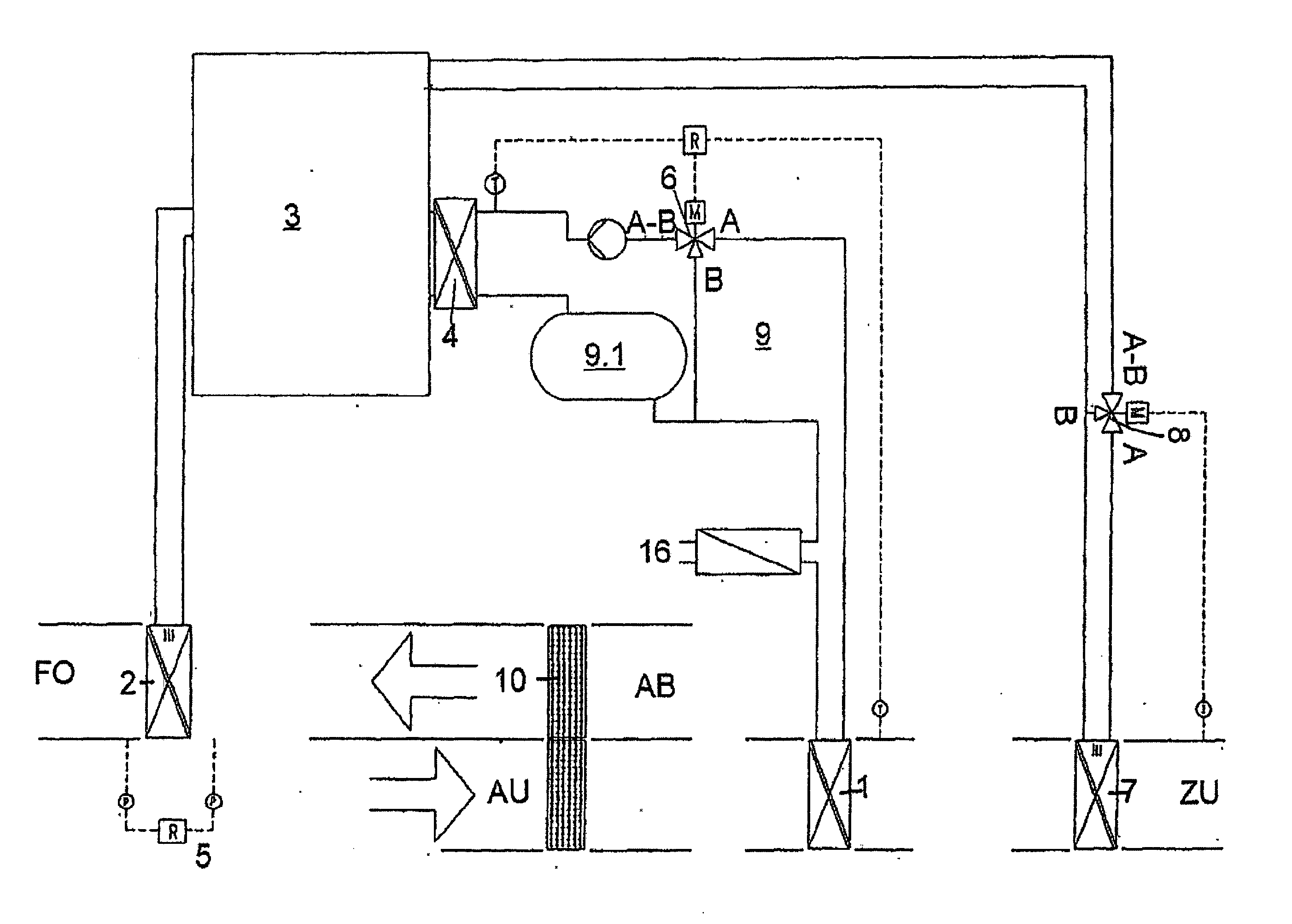
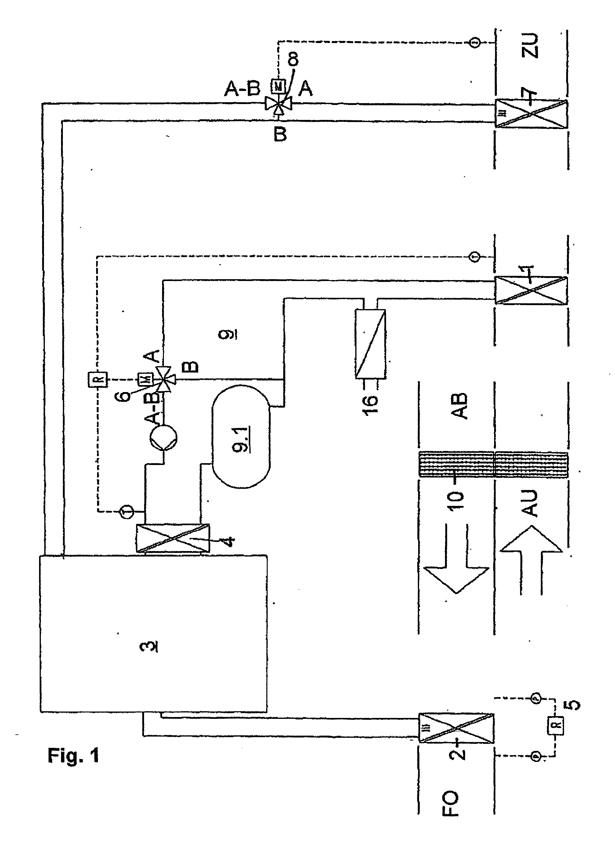
[0054] According to the invention from FIG. 1, a heat exchanger 2 is placed after a heat recovery system 10 in a used air volume flow AB, which becomes outgoing air FO through ventilation-specific handling. The heat recovery system 10 is coupled on the other side to a supply air volume flow ZU, which is obtained from the external air AU through ventilation-specific handling. The heat recovery system 10 can be formed according to one of the known configurations, e.g., as a KVS (interconnected circulating) system, rotary or plate heat exchanger, smooth tube heat exchanger, accumulator mass heat exchanger, or heat exchanger tube. The heat exchanger 2 is coupled to a heat pump 3 and in the heating case acts as an evaporator and in the optional cooling case as a condenser of the heat pump 3. In the refrigeration cycle of the heat pump 3, there is another heat exchanger 4, which is used in the heating case as a condenser, and in the cooling case as an evaporator. Furthermore, in the suppl...
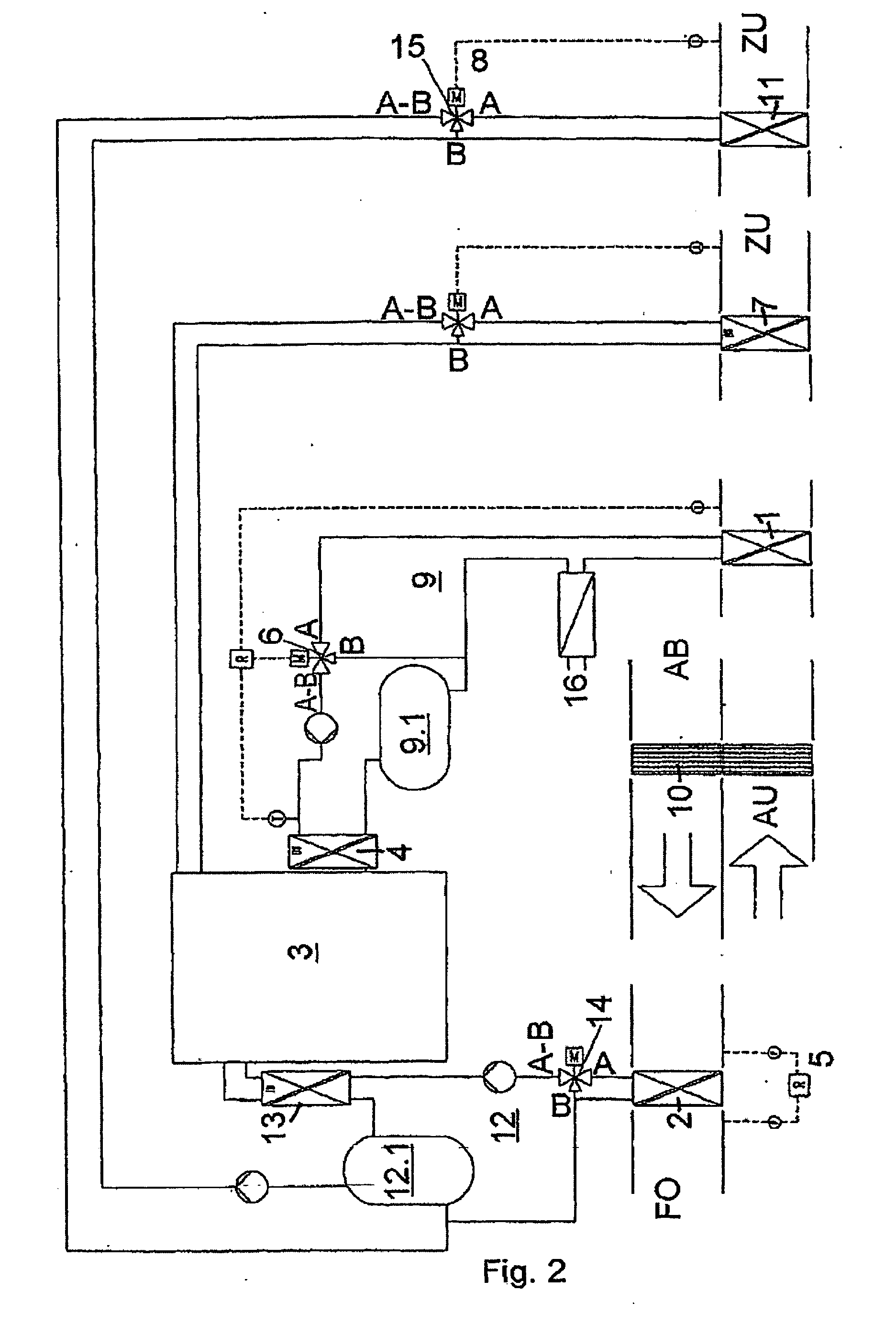
second embodiment

[0065] In the heating case, on the other hand, an optional humidity regulation of the supply air volume flow ZU is coupled to the energy accumulator 9, and is described in more detail below in the

[0066] To improve the heat dissipation in the cooling case, in the used air volume flow AB there is a device for adiabatic cooling between the heat recovery system 10 and the heat exchanger 2 of the heat pump 3. Thus, the heat transfer at this point is greatly improved in a simple manner.

[0067] To influence the air handling, air valves can be provided in the channels between the supply air volume flow ZU and the used air volume flow AB in a known way for the supply of mixed air from the used air volume flow AB to the supply air volume flow ZU or for performing an air-circulation operation, as mentioned above. For the use of mixed air, by increasing the air volume flow by means of the air valve, more thermal energy can be taken by the condenser at a lower air temperature. Thus, cold water c...


PUM


Abstract

Existing energy recovery systems are used in the fields of air conditioning and ventilation for recovering energy from the outgoing air or external air. Subsequent to an energy recovery system (10), additional thermal energy is extracted from a used air volume flow AB, which is coming from an air-conditioned room, by another system, which consists of a heat pump (3), a heat exchanger (1), another heat exchanger (2), an accumulator circuit (9), an energy accumulator (9.1), and of a mixing valve (6). The associated supply air volume flow ZU is, when heating, additionally heated by the heat pump (3) by means of thermal energy from the used air volume flow AB. This results in increasing the energy yield from the used air volume flow AB. The temperature of the supply air is regulated. When cooling, the supply air volume flow ZU is cooled to the desired supply air temperature.

Description

FIELD OF THE INVENTION [0001] The invention relates to a method for recovering energy from an air-conditioning and / or ventilation system. BACKGROUND OF THE INVENTION [0002] Heat recovery systems, systems with recuperative and regenerative heat exchangers, and also systems with an intermediate medium or heat pumps are used in air-conditioning and ventilation technology for recovering energy from the used or outgoing air. [0003] In the literature, heat recovery systems are described in many forms. Such systems are known in ventilation technology and used frequently. According to the literature, so-called return-heat indices of up to 0.8 can be achieved. [0004] In the publication “Recknagel, Sprenger, Schramek; Handbook for Heating+Air-conditioning Technology Jan. 02, 2001 edition, Oldenbourg Industrieverlag Munich” on pages 1367ff., various techniques for recovering heat are described. Among other systems, this publication also mentions a system with a heat pump. [0005] Additional clu...

Claims


Application Information

Patent Timeline
Patent Type & Authority Applications(United States)
IPC IPC(8): F24F3/00F24F12/00
CPCF24F12/003F24F2005/0025Y02B30/563Y02B30/52Y02B30/542Y02B30/54Y02B30/56
Inventor HOMBUCHER, HEINZ-DIETER
Owner HOMBUCHER HEINZ DIETER
Why Eureka
Try Eureka