Turbine Guide Apparatus

a technology of guide apparatus and guide rod, which is applied in the direction of mechanical apparatus, liquid fuel engines, pumps, etc., can solve the problems of high product variance and parts variety materialisation, and the production cost of guide apparatuses that are for example cast or produced or milled from solid materials is consequently very high, and achieves high efficiency, high shape variance, cost-effective production

Inactive Publication Date: 2019-05-23
MAN ENERGY SOLUTIONS SA
View PDF1 Cites 0 Cited by
  • Summary
  • Abstract
  • Description
  • Claims
  • Application Information

AI Technical Summary

Benefits of technology

[0005]It is therefore an object of one aspect of the present invention to overcome said disadvantages and propose a guide apparatus

Problems solved by technology

However since, dependent on the application, it is necessary to suitably adapt the guide apparatuses regarding their dimension, shape and configuration to the application, a high product variance and parts variety materialise.
Because of the required variance in blade height

Method used


Image

  • Turbine Guide Apparatus
  • Turbine Guide Apparatus
  • Turbine Guide Apparatus

Examples


Embodiment Construction

[0034]In the following, the invention is described in more detail by way of an exemplary embodiment making reference to the FIGS. 1 to 6, wherein same reference numbers refer to same structural and / or functional features.

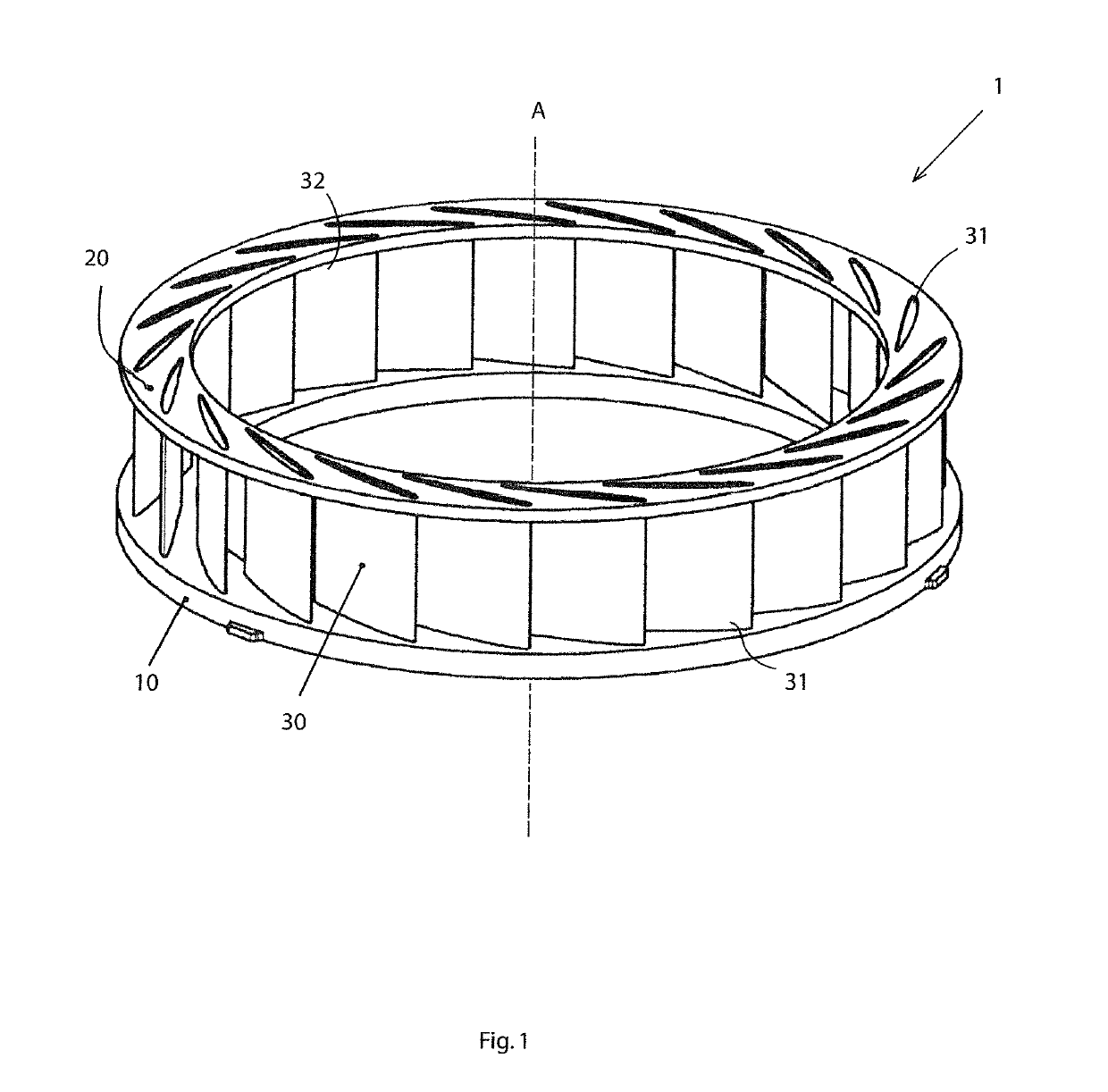
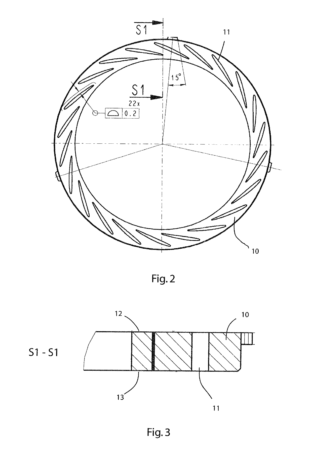
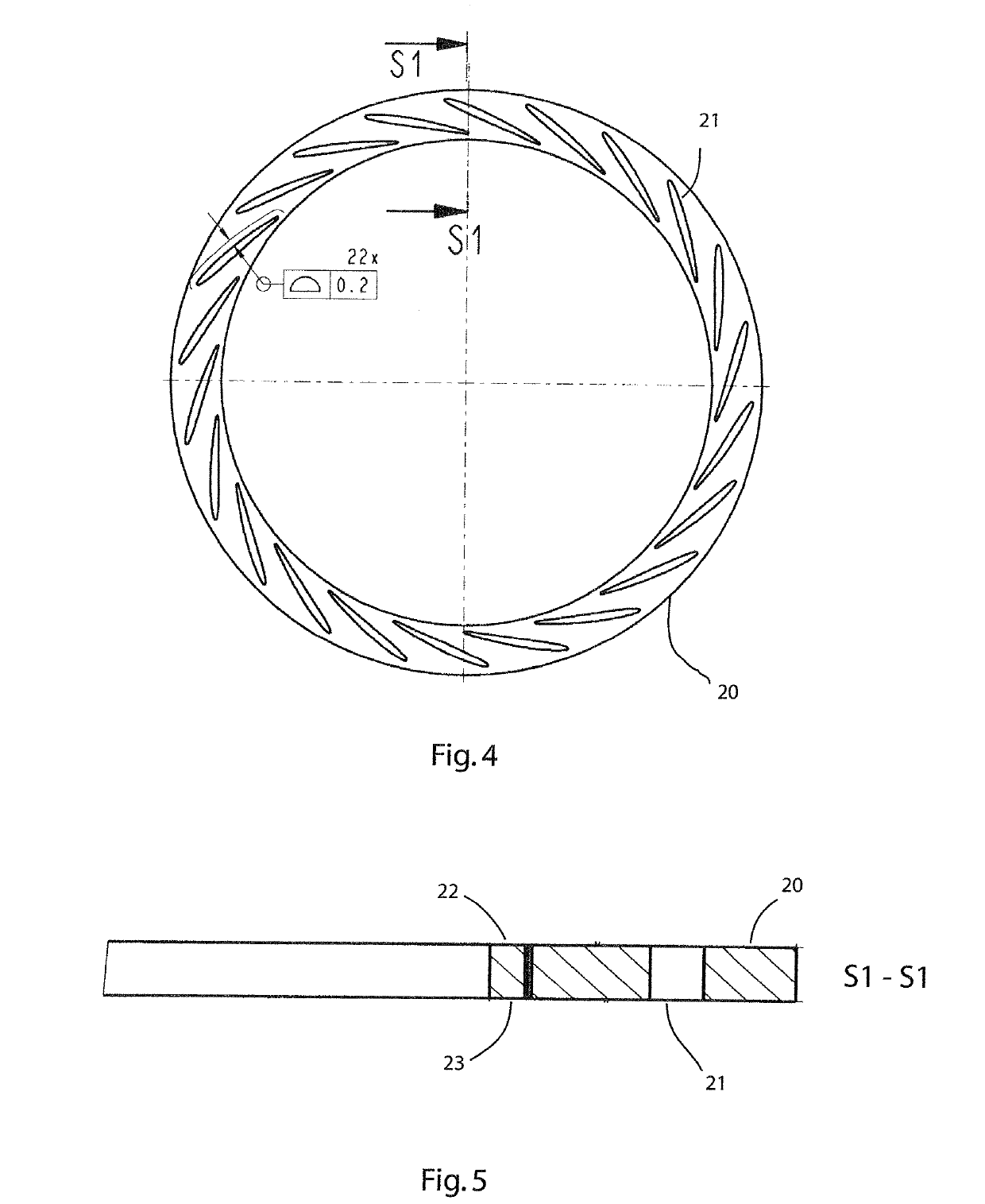
[0035]In FIG. 1, a perspective view of an exemplary embodiment of a turbine guide apparatus 1 is shown. The turbine guide apparatus 1 is assembled in multiple parts from the following components: a first annular disc element 10 (as shown in more detail in FIG. 2), a second annular disc element 20 (as shown in more detail in FIG. 4), and a multiplicity of guide blades 30, which are described in more detail with reference to FIG. 6.

[0036]The guide blades 30 are arranged between the first and second annular disc element 10, 20, wherein the guide blades 30 are connected to each annular disc element 10, 20 in this exemplary embodiment in a non-positive and positive manner, in that the same are inserted into the pocket-like recesses 11 and 21 respectively in the two annul...


PUM

PropertyMeasurementUnit
Fractionaaaaaaaaaa
Fractionaaaaaaaaaa
Fractionaaaaaaaaaa

Abstract

A turbine guide apparatus for a radial turbocharger that is assembled in multiple parts from a first annular disc element, a second annular disc element, and a multiplicity of guide blades, which are arranged between the first and second annular disc element. The guide blades are connected to each annular disc element in a firmly bonded, and/or non-positive, and/or positive manner.

Description

BACKGROUND OF THE INVENTION1. Field of the Invention[0001]The invention relates to a turbine guide apparatus, in particular a turbine guide apparatus for a radial turbocharger. The preferred field of application of the present invention relates to radial turbocompressors or radial turbochargers. In principle, the application of the invention is also conceivable for other compressors or for turbines.2. Description of the Related Art[0002]In a turbine, fluids generally flow out of one or more chambers through a transition piece and along an intended fluid path. A number of turbine stages can typically be arranged in a row along the fluid path so that the fluids flow through so-called guide apparatuses and blades of a first stage and subsequently through guide apparatuses and blades of following stages of the turbine. In this way, the turbine guide apparatuses can direct the fluids in the direction of the respective blades, as a result of which the blades are induced to rotate and for ...

Claims


Application Information

Patent Timeline
IPC IPC(8): F01D9/04F04D29/44
CPCF01D9/045F01D9/041F04D29/444F02C6/12F05D2220/40F05D2240/12F01D9/042B23P13/00
Inventor HAAS, BERNDNIEBUHR, JOHANNESDENKEL, HARALD
Owner MAN ENERGY SOLUTIONS SA
Why Eureka
Try Eureka