Optical observation system with a contactless pointer unit, operating method and computer program product

a technology of optical observation system and pointer unit, which is applied in the field of optical observation system with a contactless pointer unit, can solve the problems of high cost, large resultant error, angle error, etc., and achieve the effect of high accuracy and cost-effective production

Pending Publication Date: 2021-06-03
CARL ZEISS MEDITEC AG
View PDF0 Cites 0 Cited by
  • Summary
  • Abstract
  • Description
  • Claims
  • Application Information

AI Technical Summary

Benefits of technology

[0012]It is an object of the invention to provide an option allowing an optical observation system to be operated with a pointer device, that is, a pointer, which offers high accuracy and is producible in cost-effective fashion at the same time.

Problems solved by technology

Long pointers, in particular, can cause a significant resultant error, especially angle errors.
Therefore, there is a need for time-consuming calibrations by the user and / or for particularly dimensionally stable and precise, and hence expensive, pointers, even if the pointers could be disposable articles depending on the application.

Method used


Image

  • Optical observation system with a contactless pointer unit, operating method and computer program product
  • Optical observation system with a contactless pointer unit, operating method and computer program product
  • Optical observation system with a contactless pointer unit, operating method and computer program product

Examples


Embodiment Construction

[0055]It is understood that other embodiments can be used and structural or logical modifications can be undertaken, without departing from the scope of protection of the present invention. It is understood that the features of the various described embodiments can be combined with one another, provided there is no specific statement to the contrary.

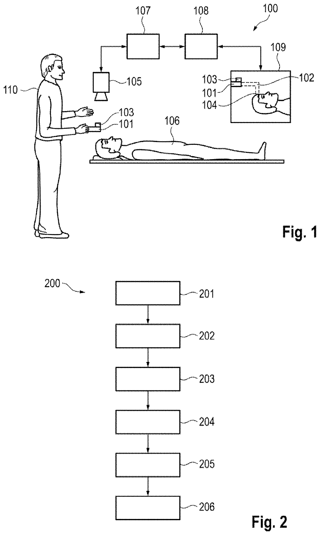
[0056]FIG. 1 shows a schematic illustration of an example of an optical observation system according to an embodiment. In the shown embodiment, the optical observation system 100 is a medical optical observation system, for example a surgical microscope system. It includes a contactless pointer unit which has a real component 101 and a virtual component 102, wherein the real component 101 includes a position labeling means 103 and the virtual component 102 has a virtual tip 104 which is at least intermittently spaced apart from the real component 101. Here, the real component 101 of the contactless pointer unit is guided by a user 110, f...


PUM


Abstract

An optical observation system includes a contactless pointer unit having a real component including a position labeling device and a virtual component including a virtual tip which is at least intermittently spaced apart from the real component. The system includes a unit for capturing at least one portion of an object and a unit for capturing a position and an alignment of the real component and a unit configured to display the captured portion of the object. The system includes a control unit for ascertaining a position of the virtual tip based on the captured position and alignment of the real component and for arranging for the image output unit to display, with a mark, the position of the virtual tip in the displayed captured portion of the object. An operating method, a pointer device suitable as a real component and a computer program product are provided.

Description

CROSS REFERENCE TO RELATED APPLICATION[0001]This application claims priority of German patent application no. 10 2019 132 308.8, filed Nov. 28, 2019, the entire content of which is incorporated herein by reference.FIELD OF THE INVENTION[0002]The present disclosure relates to an optical observation system with a contactless pointer unit and to a method for operating such an optical observation system. Moreover, the disclosure relates to computer program product and to a pointer device with a position labeling device.BACKGROUND OF THE INVENTION[0003]By way of example, an optical observation system is used in the field of medicine and includes, for example, a microscope, in particular a surgical microscope. In addition to an image recording and image reproduction unit for recording, that is, capturing, an object or portion of an object, for example a patient or an operating region, that is, a site, of a patient in the field of medicine, the optical observation system can also provide, ...

Claims


Application Information

Patent Timeline
Patent Type & Authority Applications(United States)
IPC IPC(8): G02B21/00A61B34/20A61B34/30
CPCG02B21/0012A61B34/30A61B34/20A61B90/25A61B2034/2068A61B2034/2055A61B2017/00203A61B2090/372A61B2090/502A61B2034/2065
Inventor LITSCH, DOMINIKSAUR, STEFAN
Owner CARL ZEISS MEDITEC AG
Why Eureka
Try Eureka