Wheel speed sensor for a utility vehicle

Pending Publication Date: 2022-10-06
KNORR-BREMSE SYST FUER NUTZFAHRZEUGE GMBH
View PDF0 Cites 0 Cited by
  • Summary
  • Abstract
  • Description
  • Claims
  • Application Information

AI Technical Summary

Problems solved by technology

However, a use of active wheel speed sensors has heretofore not been possible in the utility vehicle field, since a thermal stress of the sensor is greater here in the region of the wheel than in the passenger automobile field and in particular chips of Hall sensors do not withstand the thermal stress.
However, the AMR sensors have the disadvantage in relation to the Hall sensors that they only have a specific detection direction, in which a movement of a pulse generator can be detected, whereas conventional Hall sensors are not restricted to a specific detection direction, but rather can detect a movement in any direction.
Due to restrictions of the installation space, however, it

Method used


Image

  • Wheel speed sensor for a utility vehicle
  • Wheel speed sensor for a utility vehicle
  • Wheel speed sensor for a utility vehicle

Examples


Example

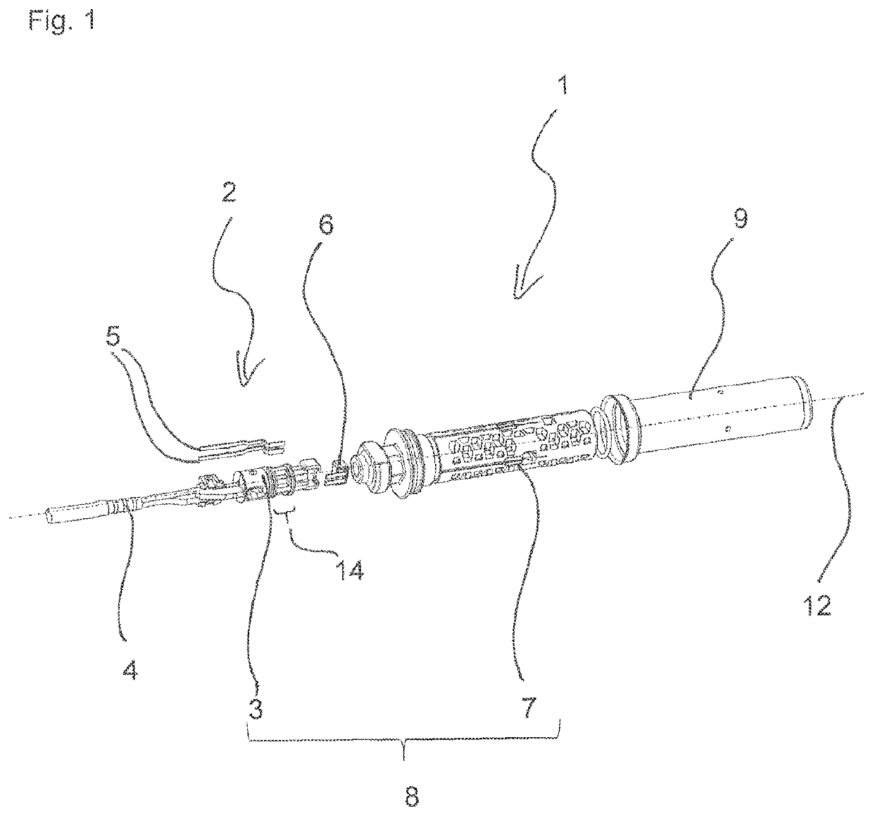
[0034]FIG. 1 shows an exploded illustration of a wheel speed sensor 1 according to the invention. The wheel speed sensor 1 has a preinstallation assembly 2.

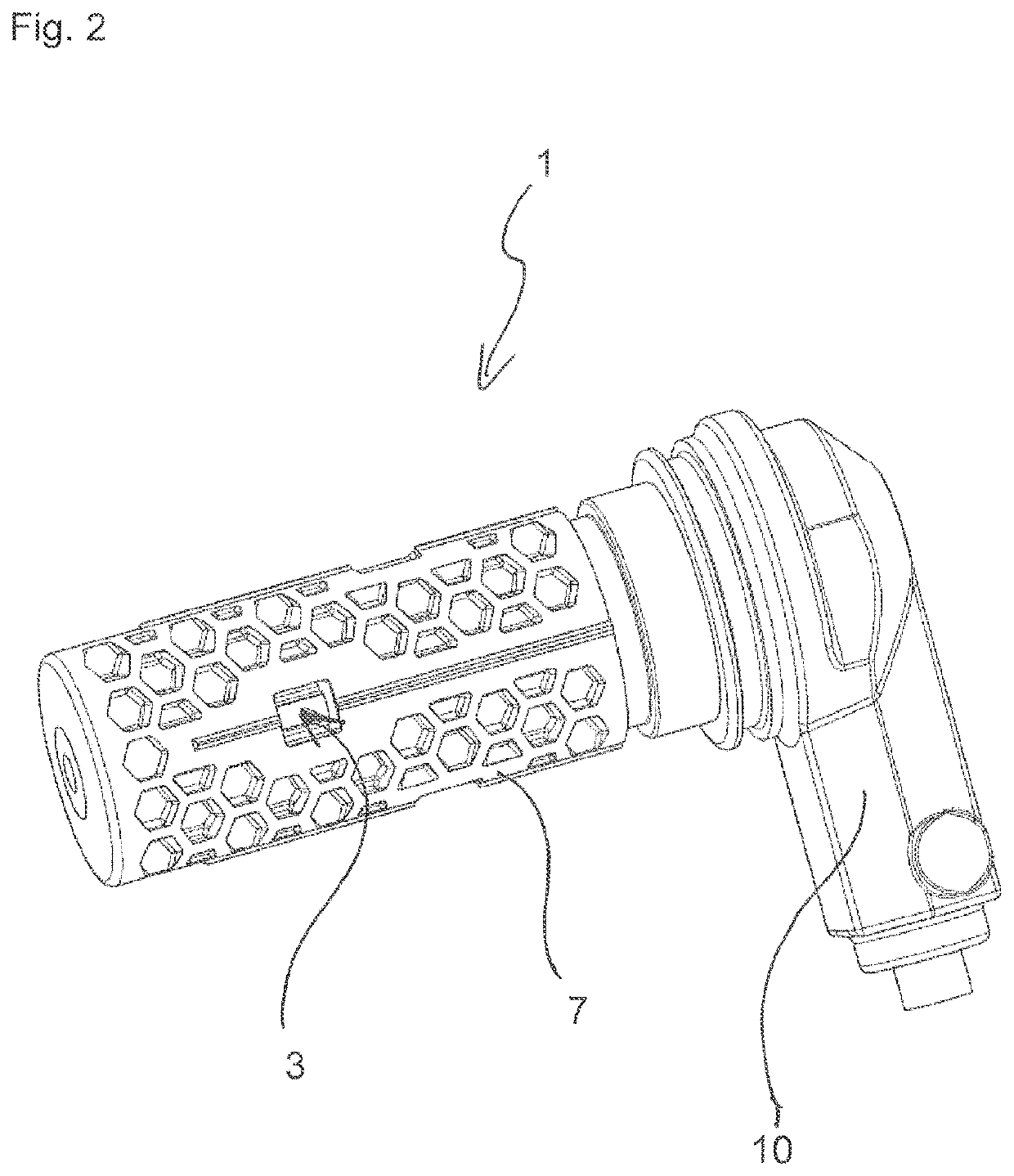
[0035]The preinstallation assembly 2 has a first component 3, a cable 4, busbars 5, and an active pulse sensor 6, which is fastened on the first component 3.

[0036]The pulse sensor 6 has a predetermined detection direction, in which a movement of a pulse generator is detectable. This is based on the effect that an electrical resistance of the pulse sensor is dependent on the presence of a magnetic field and in particular on a direction of the magnetic field. The pulse sensor 6 has an AMR sensor. In an alternative embodiment, the pulse sensor 6 is provided with another sensor having a predetermined detection direction, for example, an active Hall sensor.

[0037]The first component 3 is produced by a casting process, in which the busbars 5 are embedded in the first component 3, so that the first component 3 is formed as a plastic mold...


PUM


Abstract

A wheel-speed sensor (WSS), including: an active pulse-sensor (PS) having a detection-direction (DD), and a housing for the PS; a movement of a pulse-generator in the DD is detectable by the PS; the WSS has an axis and axis direction (AD) defined to be aligned perpendicularly to the DD; the housing has first/second-components, the first-component (FC) being enclose-able and to which the FC is connectable; the PS is on the FC; the WSS has a radial-cable-outlet (RCO), aligned radially to the axis to lead a cable out; the RCO integrally formed with the second-component (SC) so that the cable is led in a different direction; the FC has a first-region (FR), and the SC has a second-region (SR), the FR-contour-circumference having a shape-feature in predetermined-angle (PA) steps around the axis, so that an FC orientation is definable in the PA steps to provide a PA around the axis.

Description

FIELD OF THE INVENTION[0001]The invention relates to a wheel speed sensor for a utility vehicle, in particular a wheel speed sensor for a utility vehicle which is arranged in the region of a brake of a wheel on a chassis of the utility vehicle.BACKGROUND INFORMATION[0002]It is believed to be necessary to detect wheel speeds of individual wheels of vehicles to enable a function of assistance systems, for example, ABS, ASR, or ESP. An accurate detection is necessary to activate appropriate algorithms in borderline situations. To detect the wheel speeds accurately, wheel speed sensors are known which are arranged in the region of a wheel of the vehicle to detect the speed as directly as possible, without deviations due to a mechanical transmission.[0003]In the passenger vehicle field, active wheel speed sensors are increasingly being used, which already generate signals in the wheel speed sensor, which have, for example, a speed-independent constant amplitude. Therefore, a data protoco...

Claims


Application Information

Patent Timeline
IPC IPC(8): G01P3/487G01P1/02G01D5/14G01R33/07
CPCG01P3/487G01P1/026G01D5/142G01R33/072B60T8/171B60T8/76
Inventor KLUFTINGER, ANDREWINDISCH, ANDREASLECHNER, KLAUSJAWARIKAR, PRAVINHAUFF, MICHAELROHSE, TOBIAS
Owner KNORR-BREMSE SYST FUER NUTZFAHRZEUGE GMBH
Why Eureka
Try Eureka