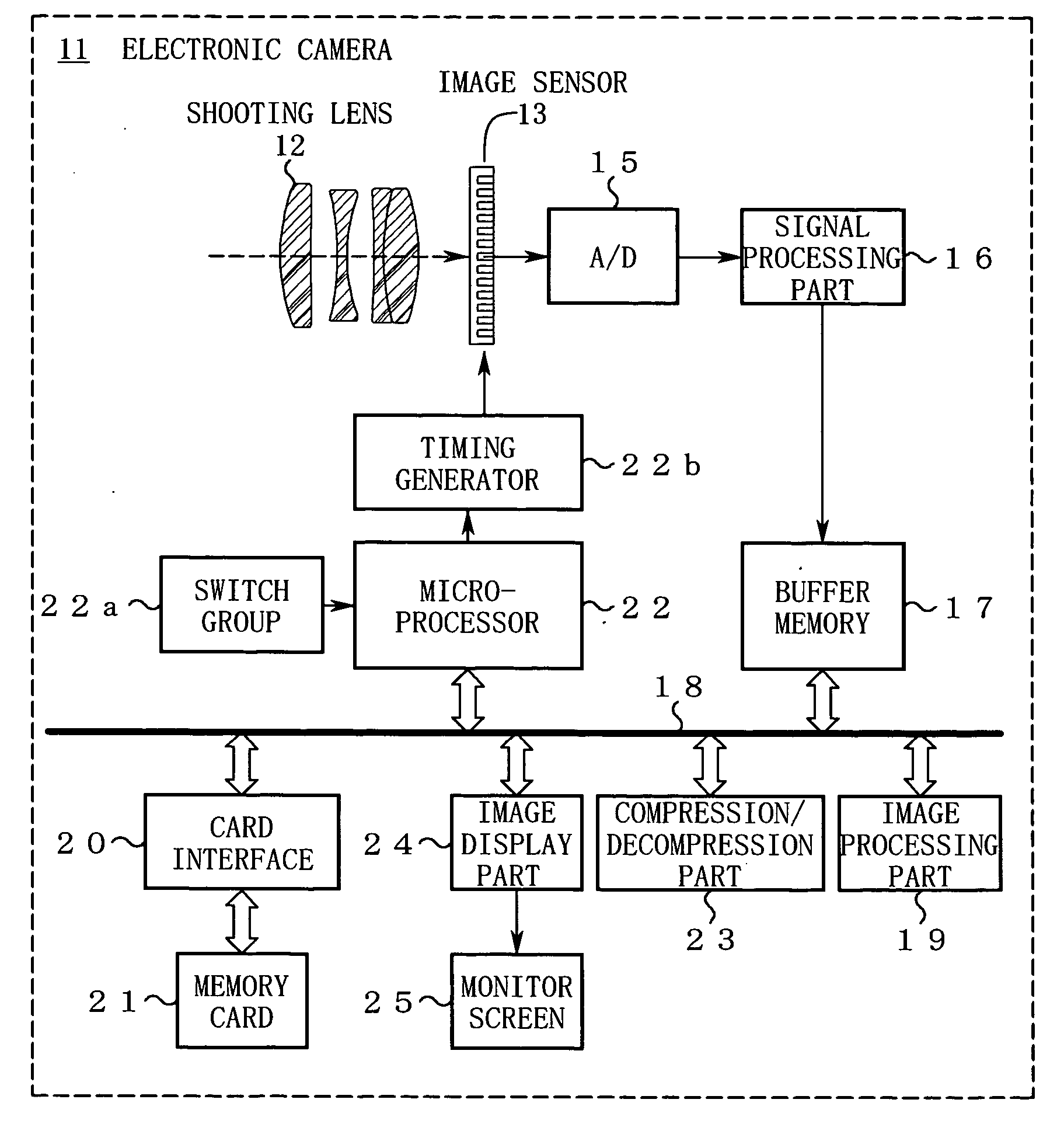
Image-processing devices, methods, and programs, and electronic cameras and the like comprising same
a technology of image processing and image processing program, which is applied in the direction of image enhancement, color signal processing circuit, instruments, etc., can solve the problems of difficult to correct the gradation of an image having extremely bright and dark portions, placing the entire image in poor gradation, and the color of the bright portion to be too white, etc., to suppress excessive brightness, enhance the gradational change of an image, and suppress unnatural brightness in large shadow areas
- Summary
- Abstract
- Description
- Claims
- Application Information
AI Technical Summary
Benefits of technology
Problems solved by technology
Method used
Image

Examples
first embodiment
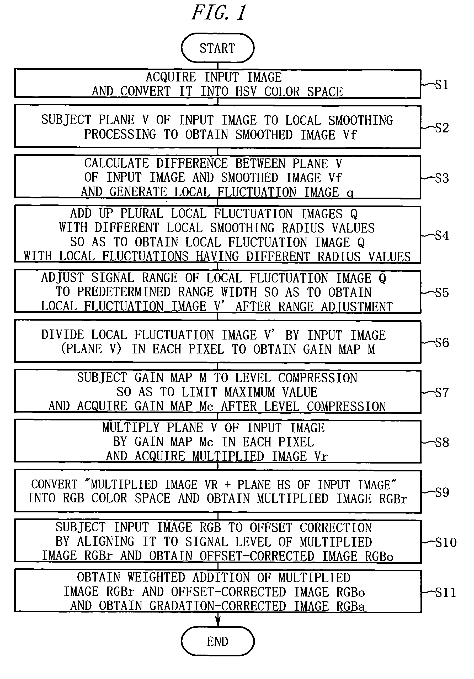
[0034]FIG. 1 is a diagram for explaining image processing according to the first embodiment. The image-processing as performed by a computer will be described in the order of the step numbers shown in FIG. 1.
[0035] Step S1: The computer receives or otherwise obtains an input image RGB (the number of horizontal pixels is W, the number of vertical pixels is P) in RGB color space and converts it into an image in HSV color space.
[0036] Step S2: The computer subjects a V plane, indicating the luminance (brightness) component of each pixel of the input image, to local-smoothing processing and produces a smoothed image Vf. For example, after setting a radius r of local smoothing, the computer first performs local smoothing in the horizontal direction of the frame using initial values and recurrence formulas as follows. Initial values:
S(0, y)=rV(0, y)+V(0, y)+ . . . +V(r, y) [1]
Vz(0, y)=S(0, y) / (2r+1) [2]
Recurrence Formulas:
S(x, y)=S(x−1, y)−V(x−1−r, y)+V(x+r, y) [3]
Vz(x, y)=S(x, y) / (...
second embodiment
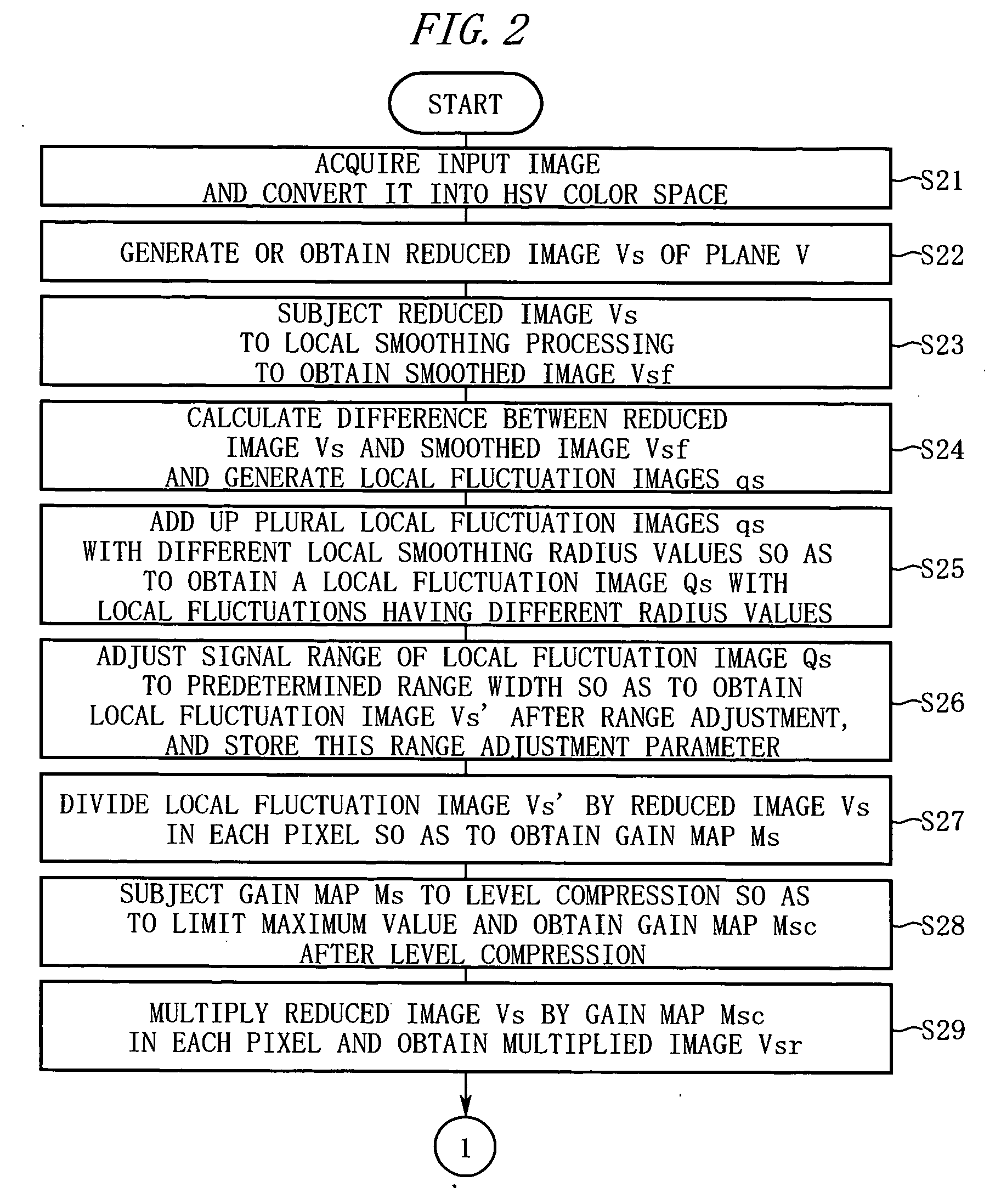
[0063]FIG. 2 and FIG. 3 are diagrams for explaining the operation of an image-processing program according to this embodiment. The image-processing operation as performed by a computer will be described below in the order of the step numbers shown in these figures.
[0064] Step S21: The computer inputs an image RGB (the number of horizontal pixels is W, the number of vertical pixels is P) in the RGB color space and converts it into the HSV color space.
[0065] Step S22: The computer performs a resolution-conversion with respect to the V plane of the input image and generates a reduced image Vs in which the number of longitudinal and transverse pixels is reduced. When the reduced image is recorded in advance in the file of the input image, it is possible to obtain the reduced image Vs by converting the reduced image in the file into the HSV color space.
[0066] Steps S23 to S32: The computer obtains a gain map Msc after the level-compression and obtains a gradation-corrected image RGBsa...
third embodiment
[0077] A third embodiment is characterized by saturation-adjustment for reflecting a gain map in an image, etc. The operations in the third embodiment are described below.
[0078] First, the computer performs the operations in steps S1 to S6 in the first embodiment and thereby obtains a gain map M. The computer level-compresses the gain map M using the following formula:
Mc(x, y)=Mmax·(x, y) / [Mmax2+M(x, y)2]1 / 2 [13′]
wherein Mmax is the maximum value after the level-compression. It is desirable to set Mmax to about six so as not to collapse the color balance when the gain map is reflected in the image.
[0079] Next, the computer obtains the multiplied RGBr by reflecting the gain map Mc after the level-compression in the input image RGB in accordance with the following formulas:
Rr(x, y)=R(x, y)+V(x, y)[Mc(x, y)−1][R(x, y) / V(x, y)]Psat
Gr(x, y)=G(x, y)+V(x, y)[Mc(x, y)−1][G(x, y) / V(x, y)]Psat
Br(x, y)=B(x, y)+V(x, y)[Mc(x, y)−1][B(x, y) / V(x, y)]Psat [14′]
wherein Psat is a saturation-adj...
PUM
 Abstract
Description
Claims
Application Information