Depth of field enhancement for optical comparator

a technology of depth of field and optical comparator, which is applied in the direction of measurement devices, instruments, structural/machine measurement, etc., can solve the problems of difficult to measure three-dimensional objects that need more than one surface in focus at the same time, increase in depth of field, etc., to reduce confusion circle, increase the depth of field, increase the effect of field

Inactive Publication Date: 2007-01-16
BAUSCH & LOMB INC
View PDF6 Cites 0 Cited by
  • Summary
  • Abstract
  • Description
  • Claims
  • Application Information

AI Technical Summary

Benefits of technology

[0007]The present invention addresses the shortcomings in the prior art that have a larger circle of confusion as a result of employing a large aperture. Instead, the invention uses a narrow aperture on a magnifying objective lens in order to reduce the circle of confusion and increase the depth of field compared to prior artdevices. Using a smaller aperture results in a smaller circle of confusion resulting in an increase in depth of field allowing simultaneous focus of entire objects. The trade-off made using a narrow aperture is that there is less light that can pass through a narrow aperture compared to a large aperture resulting in less brightness within the system using the narrow aperture. The advantage is that the depth of field is increased. Prior art inspection devices employ large apertures resulting in more brightness but less depth of field. The lack of depth of field in conventional two-dimensional inspection devices makes it difficult to measure three-dimensional objects that need more than one surface in focus the same time. This invention addresses the problem by increasing the depth of field by a significant amount.
[0008]The invention provides a narrow aperture behind the objective lens. This narrow aperture reduces the optical circle of confusion, thereby increasing the focal range, leading to a greater depth of field. The size of the aperture can be varied to change the depth of field to a desired amount. The use of a narrow aperture requires a brighter light source. Since the narrow aperture placed on the objective lens blocks out the majority of light passing through the lens, the resulting image on the screen can be a very dark image. The use of the arc lamp (or another lamp with sufficient light intensity that does not alter the intent of this invention) and a condenser lens focuses a more intense beam of light through the objective lens, thereby creating a brighter image without sacrificing any depth of field. The use of a smooth elliptical reflector on the arc lamp helps to focus the most light possible through the condenser lens, and consequently through the objective lens.

Problems solved by technology

Using a smaller aperture results in a smaller circle of confusion resulting in an increase in depth of field allowing simultaneous focus of entire objects.
The lack of depth of field in conventional two-dimensional inspection devices makes it difficult to measure three-dimensional objects that need more than one surface in focus the same time.

Method used


Image

  • Depth of field enhancement for optical comparator
  • Depth of field enhancement for optical comparator
  • Depth of field enhancement for optical comparator

Examples


Embodiment Construction

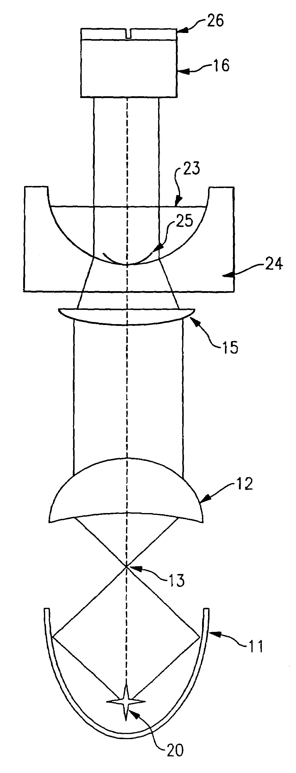
[0012]The purpose of the invention is to acquire an image of the entire contact lens at once. This enables detection of scratches on virtually any portion of the lens. Scratches on the edges or scratches in the middle can be detected in a single step. The invention allows for inspection of the entire contact lens at one time, simultaneously looking for scratches and other defects that exist on either surface or any edge. The preferred embodiment of the invention projects an image magnified ten times on a display screen.

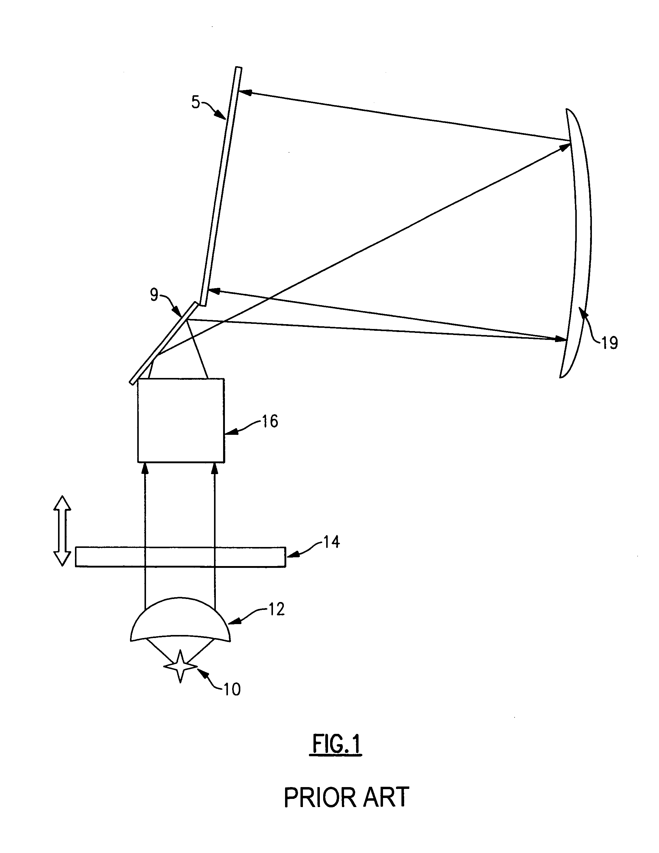
[0013]The lack of a depth of field in a prior art two-dimensional inspection device makes it difficult to measure three-dimensional objects that require more than one surface to be inspected. It is, therefore, highly desirable to have the entire object in focus the same time. This invention addresses the problem by increasing the depth of field by a significant amount.

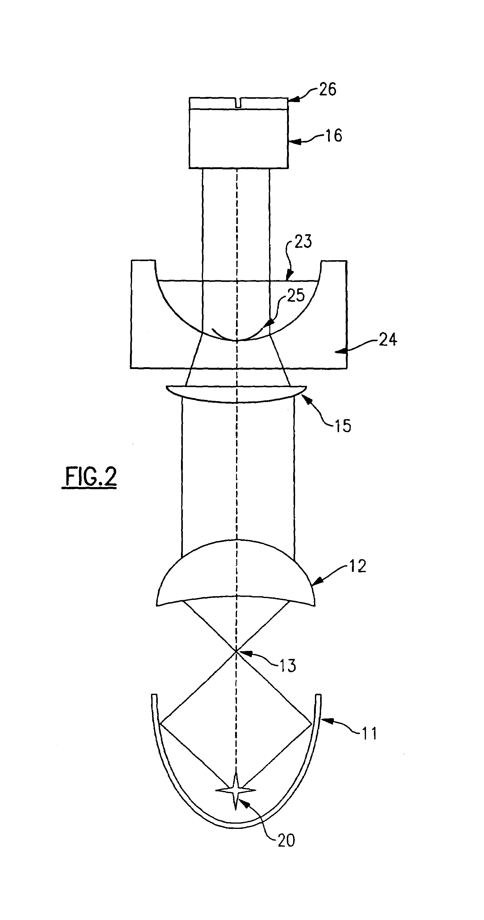
[0014]Referring to FIG. 2, the present invention simultaneously focuses on the entire contact lens by...


PUM


Abstract

An optical device inspection system and method employing a narrow aperture on a magnifying objective lens in order to reduce the circle of confusion and increase the depth of field. The smaller aperture resulting in an increase in depth of field allows for simultaneous focus for all portions of objects being inspected. An arc lamp with an elliptical reflector in combination with a condenser lens focuses a more intense beam of light through the objective lens, thereby providing sufficient brightness without sacrificing any depth of field.

Description

BACKGROUND OF THE INVENTION[0001]1. Field of the Invention[0002]The present invention pertains to inspection devices, and more particularly, to inspection devices that are used for contact lenses.[0003]2. Description of the Prior Art[0004]Currently available inspection devices employ image-capturing technology. There are many types of image-capturing devices within the prior art. The size of the apertures used on these prior art devices can range from small apertures to large apertures. It is well known within the imaging arts that a greater depth of field results from using a smaller aperture. Examples of imaging devices that use small apertures are single-use cameras and WebCams. Small apertures are very useful in providing simultaneous focus of objects from three feet to infinity. A shortcoming in the application of small apertures is that only a small amount of light can pass through the small aperture. Imaging devices having small apertures typically require brighter light as c...

Claims


Application Information

Patent Timeline
Patent Type & Authority Patents(United States)
IPC IPC(8): G01B9/00G01M11/02
CPCG01M11/0207
Inventor BERGENDAHL, MARCLEWISON, DAVIDPUFFER, JR., RAYMOND H.
Owner BAUSCH & LOMB INC
Why Eureka
Try Eureka