System and method for detecting power system conditions

a power system and detection system technology, applied in the field of power system monitoring, can solve the problems of inadvertent disconnection of one or more portions of the power system however undesirable, undesirable decrease or increase in the frequency of the power system, loss of available power for motor starting,

Active Publication Date: 2007-05-03
SCHWEITZER ENGINEERING LABORATORIES
View PDF7 Cites 40 Cited by
  • Summary
  • Abstract
  • Description
  • Claims
  • Application Information

AI Technical Summary

Benefits of technology

[0012] It should be understood that the present invention includes a number of different aspects or features which may have utility alone and/or in combination with other aspects or features. Accordingly, this summary is not exhaustive identification of each such aspect or feature that is now or may he

Problems solved by technology

Inadvertent disconnection of one or more portions of the power system however is undesirable.
As a result of islanding, power generation and loads may not balanced, thereby causing undesirable decreases or increases in the power system frequency, loss of available power for motor starting, or loss of coordination of the protective device, to name a few.
At a minimum, islanding causes a loss of generation and load diversity and therefore reduces power system reliability.
In cases where power system operators are unaware of the existence of one or more the power system “islands” or are unable to pin-point boundarie

Method used


Image

  • System and method for detecting power system conditions
  • System and method for detecting power system conditions
  • System and method for detecting power system conditions

Examples


Embodiment Construction

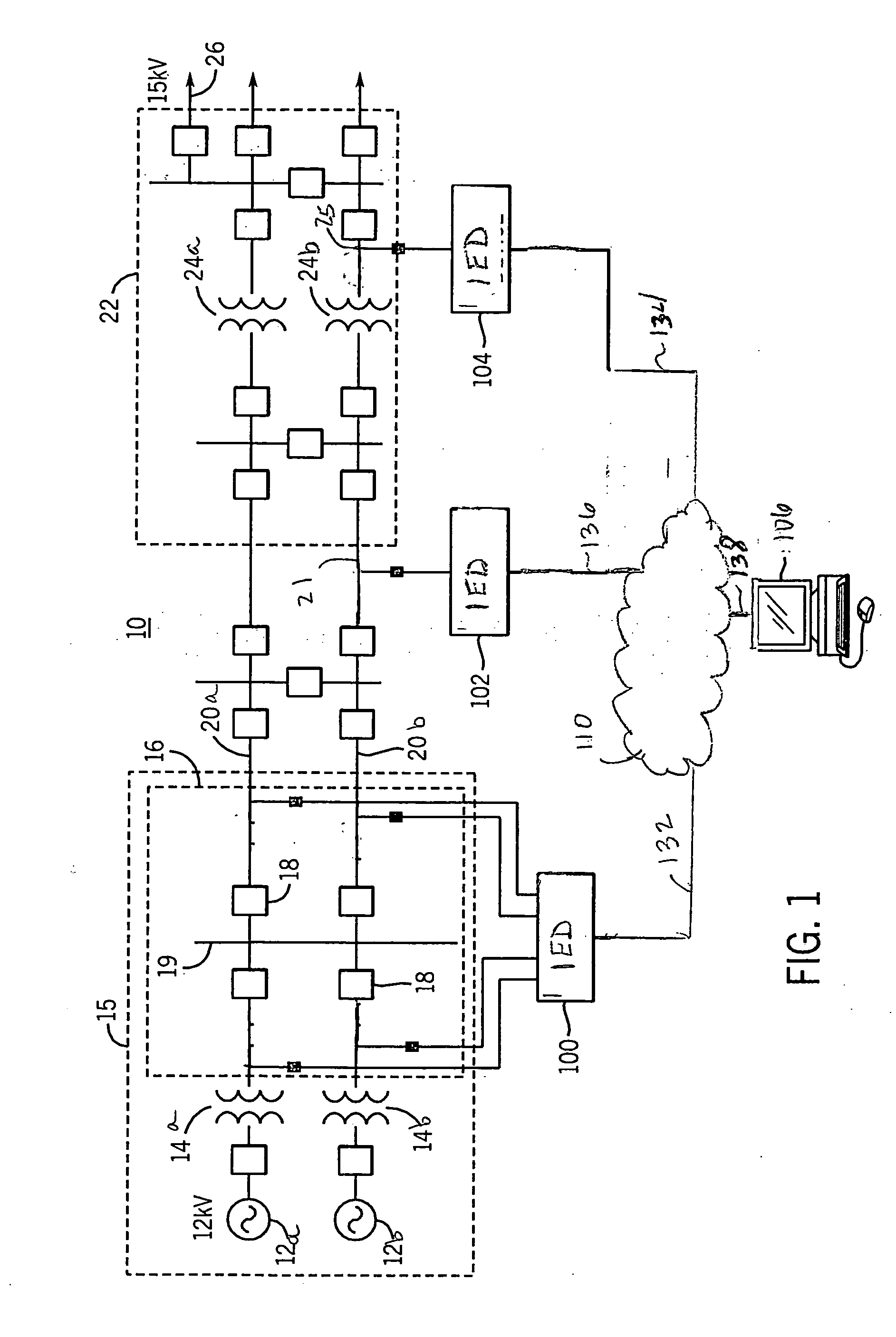
[0019]FIG. 1 is a single line schematic diagram of a power system 10 that may be utilized in a typical wide area. As illustrated in FIG. 1, the power system 10 includes, among other things, two generators 12a and 12b, configured to generate three-phase sinusoidal waveforms such as 12 kV sinusoidal waveforms, two step-up power transformers 14a and 14b, configured to increase the generated waveforms to a higher voltage sinusoidal waveforms such as 138 kV sinusoidal waveforms and a number of circuit breakers 18. The step-up power transformers 14a and 14b operate to provide the higher voltage sinusoidal waveforms to a number of long distance transmission lines such as the transmission lines 20a and 20b. In an embodiment, a first substation 15 may be defined to include the two generators 12a and 12b, the two step-up power transformers 14a and 14b and associated circuit breakers 18, all interconnected via a first bus 19. At the end of the long distance transmission lines 20a, 20b, a secon...


PUM


Abstract

Provided is a system and method for detecting a power system condition of a power system. The system includes at least a first and second intelligent electronic device (IED) operatively coupled to the power system at respective first and second power system locations. Each IED is configured to calculate a measured time value based on a frequency dependant parameter such as a secondary voltage signal at their respective locations, to compare the measured time value to a reference time value to form a time error, and to transmit the time error. The system further includes a third IED configured to compare respective time errors received from the first and second IEDs to form a time differential error, to map the time differential error back to their power system locations, and compare the time differential error to a predetermined threshold to determine the power system condition.

Description

CROSS-REFERENCE TO RELATED APPLICATIONS [0001] This application claims benefit under 35 U.S.C. §119(e) of U.S. Provisional Application entitled “System and Method for Detecting Power System Conditions”, filed on Oct. 21, 2005, naming Roy E. Moxley as inventor, the complete disclosure thereof being incorporated by reference.BACKGROUND OF THE INVENTION [0002] The present invention generally relates to power system monitoring, and more specifically, to a system and method for detecting power system conditions. [0003] Electric utility systems or power systems are designed to generate, transmit and distribute electrical energy to loads via a variety of power system elements such as electrical generators, power transformers, power transmission lines, distribution lines, buses and capacitors, to name a few. As a result, power systems are typically monitored and protected using a number of different types of protective devices having associated protective schemes. Such protective schemes pr...

Claims


Application Information

Patent Timeline
IPC IPC(8): H02J13/00
CPCH02H3/46H02H3/48H02H7/261
Inventor MOXLEY, ROY E.
Owner SCHWEITZER ENGINEERING LABORATORIES
Why Eureka
Try Eureka