Keyboard structure and keyboard assembly method

Inactive Publication Date: 2007-05-10
JENSIN INTL TECH CORP
View PDF4 Cites 5 Cited by
  • Summary
  • Abstract
  • Description
  • Claims
  • Application Information

AI Technical Summary

Benefits of technology

[0008] Accordingly, the present invention is directed to a keyboard

Problems solved by technology

However, the labor cost of manual as

Method used


Image

  • Keyboard structure and keyboard assembly method
  • Keyboard structure and keyboard assembly method
  • Keyboard structure and keyboard assembly method

Examples


Example

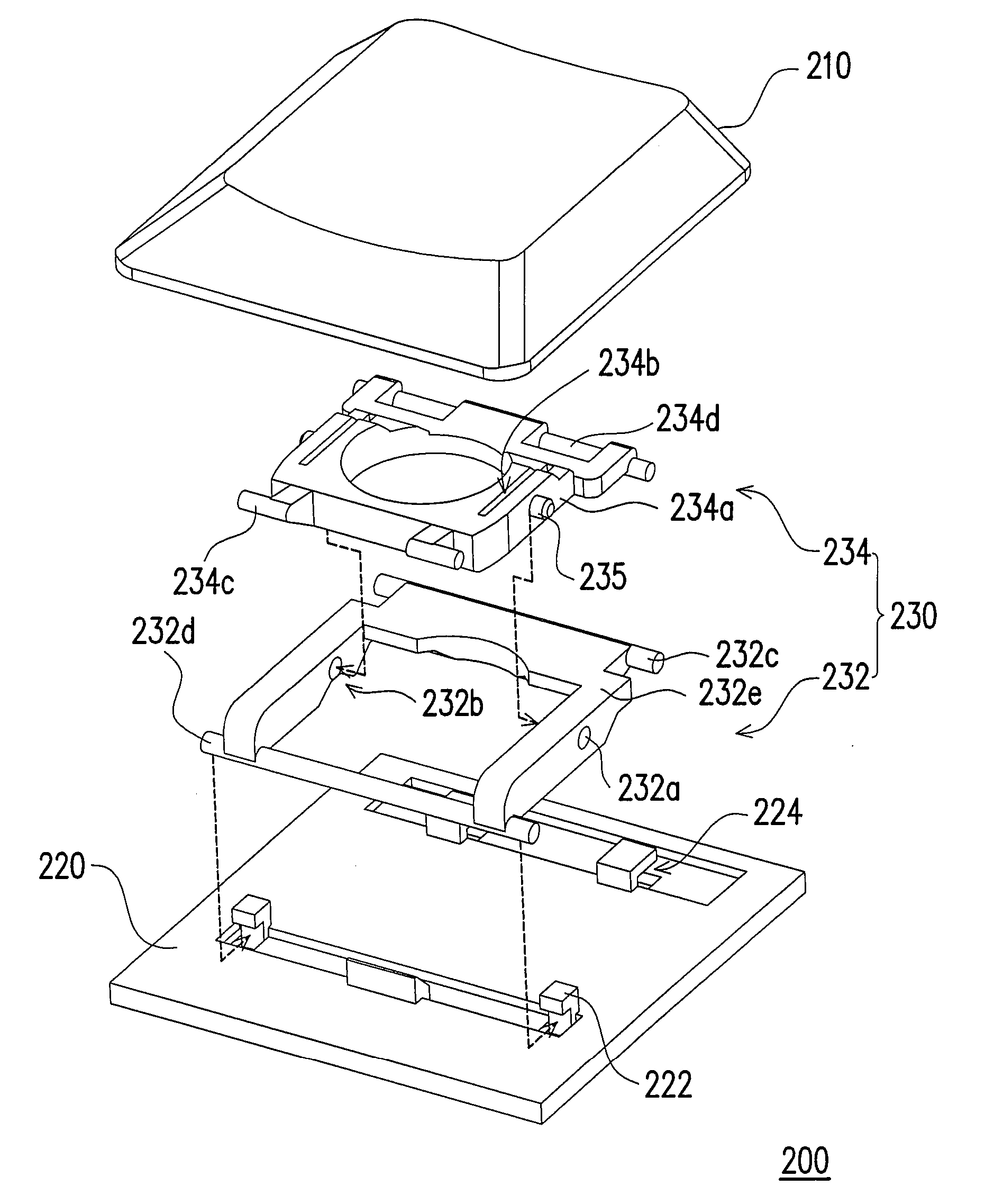
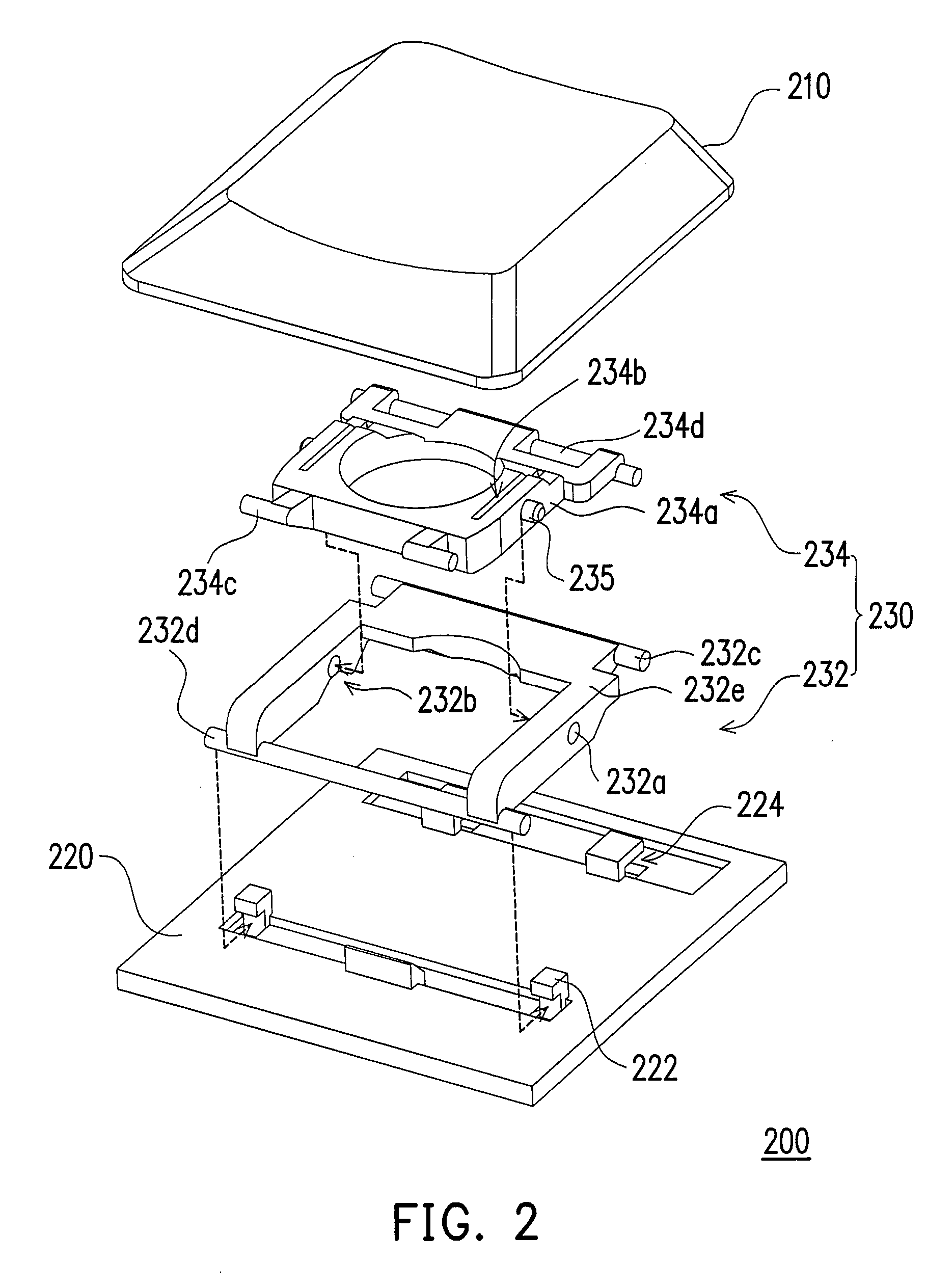
[0026]FIG. 2 is an exploded diagram of a keyboard structure according to an embodiment of the present invention. FIG. 3 is an exploded diagram illustrating the cross pivoting between the first frame and the second frame in FIG. 2. Referring to both FIG. 2 and FIG. 3, the key board structure 200 includes a key-cap 210, a base 220, and a linking-up mechanism 230. Wherein the key-cap 210 is disposed on the base 220, and the linking-up mechanism 230 is connected between the base 220 and the key-cap 210. The linking-up mechanism 230 includes a first frame 232 and a second frame 234. The first frame 232 is pivoted to the base 220. The first frame 232 has two openings 232a and two guide slots 232b on the two opposite sides thereof, and the openings 232a are connected correspondingly to the guide slots 232b. The second frame 234 is connected to the key-cap 210. The first frame 232 and the second frame 234 are pivoted crosswise. In addition, the second frame 234 has two pivotal arms 234a and...


PUM


Abstract

A keyboard structure including a base, a key-cap, and a linking-up mechanism is provided. The key-cap is disposed on the base, and the linking-up mechanism is connected between the base and the key-cap. The linking-up mechanism includes a first frame and a second frame. The first frame is connected to the key-cap. The first frame has two openings and two guide slots on two opposite sides, and the openings are connected to the guide slots correspondingly. The second frame is pivoted to the base, and the first frame is pivoted to the second frame crosswise. The second frame has two pivotal arms and two open slots on two opposite sides. Each pivotal arm has a fixing protrusion pivoted in the opening.

Description

CROSS-REFERENCE TO RELATED APPLICATION [0001] This application claims the priority benefit of Taiwan application serial no. 94138722, filed Nov. 4, 2005. All disclosure of the Taiwan application is incorporated herein by reference. BACKGROUND OF THE INVENTION [0002] 1. Field of the Invention [0003] The present invention relates to a keyboard structure and an assembly method thereof. More particularly, the present invention relates to a keyboard structure suitable for automatic assembly and an automatic assembly method thereof. [0004] 2. Description of Related Art [0005] Electronic products have been applied broadly in our daily life along with the development of technology. Some commonly used electronic apparatuses include cell phone, electronic dictionary, personal digital assistant (PDA), personal computer (PC), and notebook computer (NB), etc. [0006] Taking PC as an example, the usually a keyboard is used for inputting data into the PC and then the data conveniently stored into t...

Claims


Application Information

Patent Timeline
IPC IPC(8): H01H13/70
CPCH01H3/125
Inventor LIU, HUNG-CHIEH
Owner JENSIN INTL TECH CORP
Why Eureka
Try Eureka