Camera

a technology for cameras and cameras, applied in the field of cameras, can solve the problems of increasing the size of display sections, improving the gripability of such digital cameras, and the overall size of the digital camera, so as to improve the gripability and the effect of improving the grip during photography/image playback

Inactive Publication Date: 2007-05-10
FUJIFILM CORP
View PDF10 Cites 14 Cited by
  • Summary
  • Abstract
  • Description
  • Claims
  • Application Information

AI Technical Summary

Benefits of technology

[0026] According to the display device of the present invention, by providing the second assembly on the first assembly so as to be movable between the first position at which the operation members are covered and the second position at whi

Problems solved by technology

In digital cameras provided with display sections such as liquid crystal monitors, the increase in size of display sections has created conflicting issues of improvement in gripability of such digital cameras and downsizing of the camera main bodies.
Keeping such photography operation buttons visible to a user even during a playback mode which does not require operating these buttons may cause erroneous operations, and ther

Method used


Image

  • Camera
  • Camera
  • Camera

Examples


first embodiment

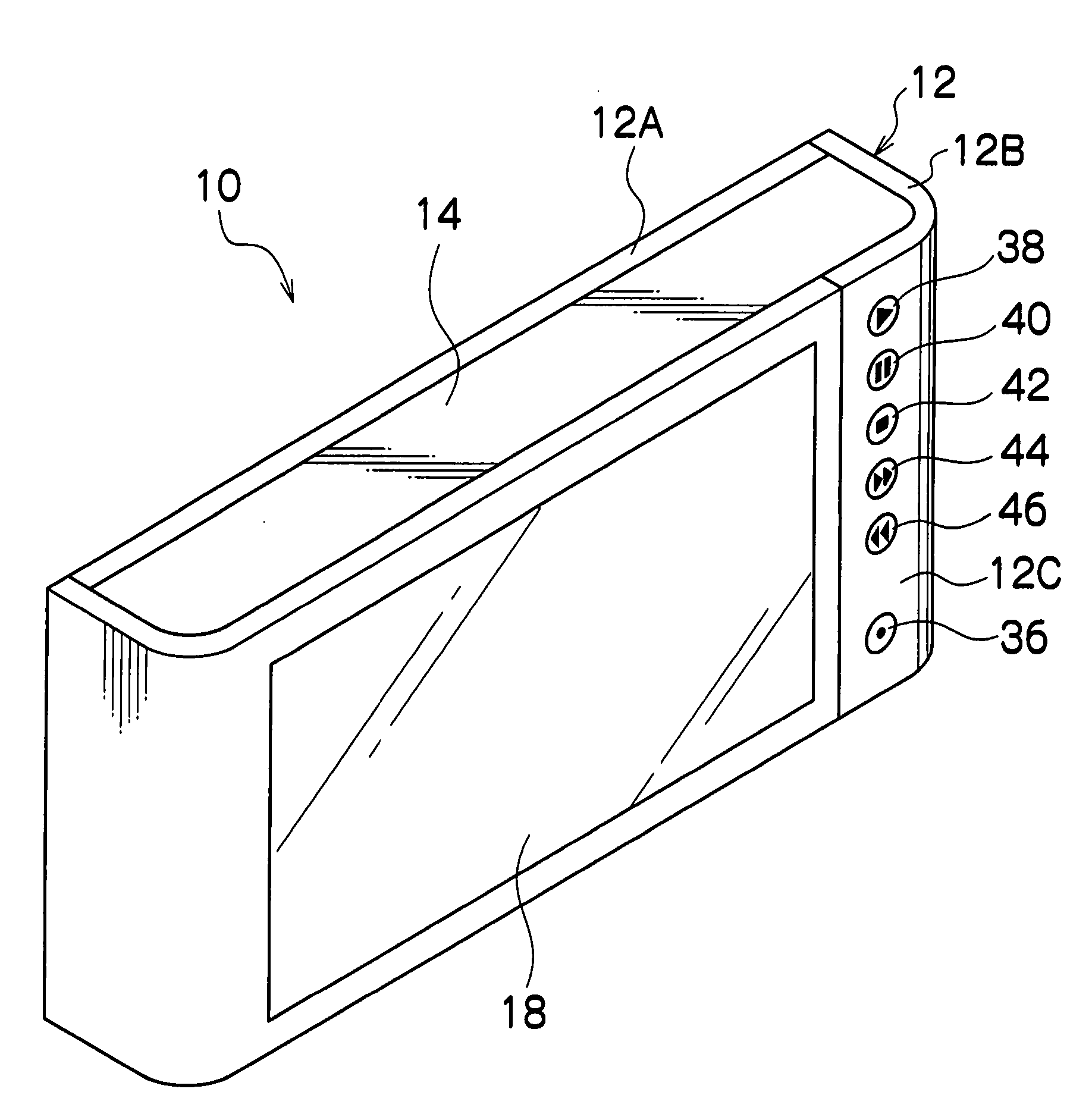
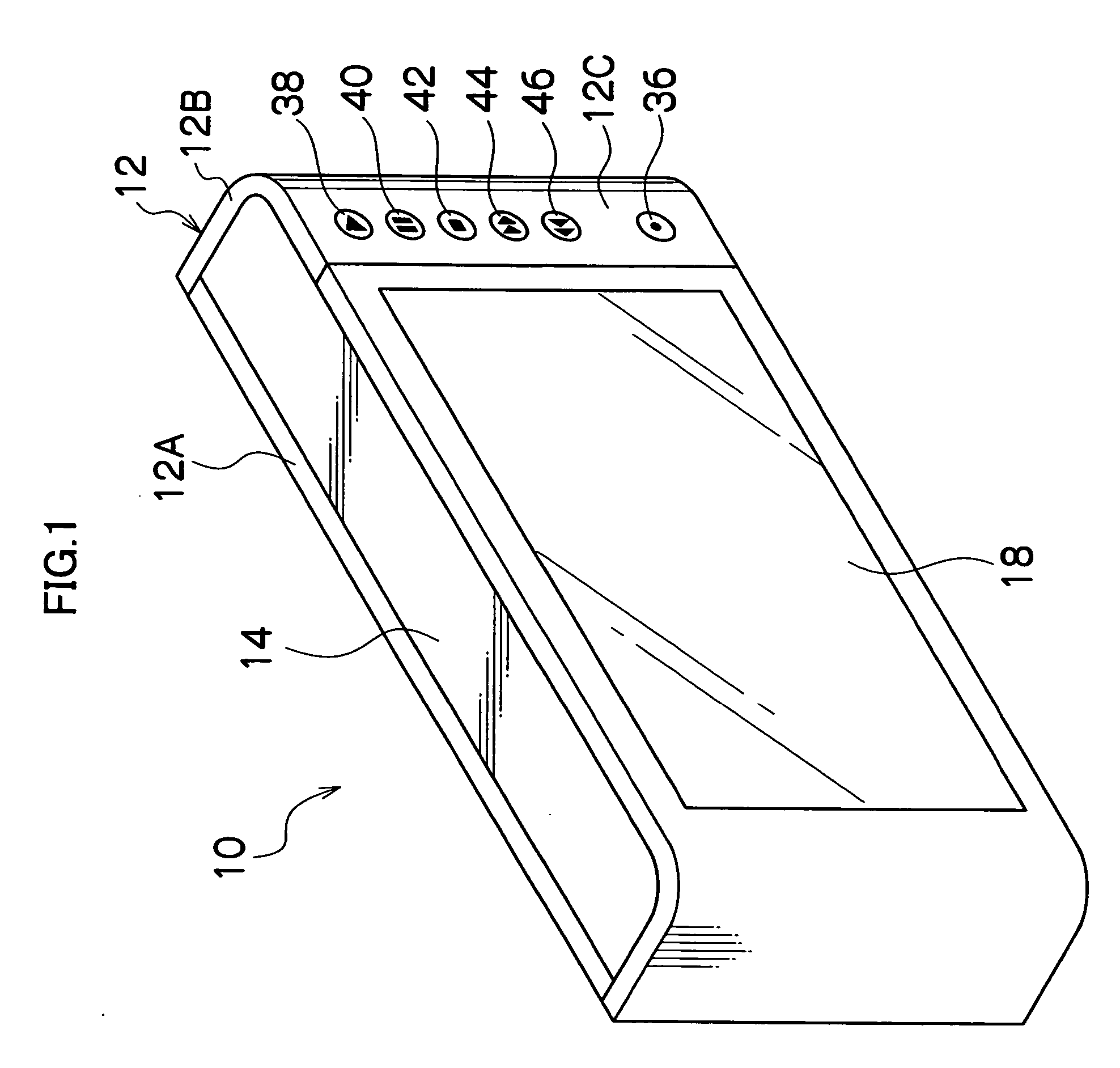
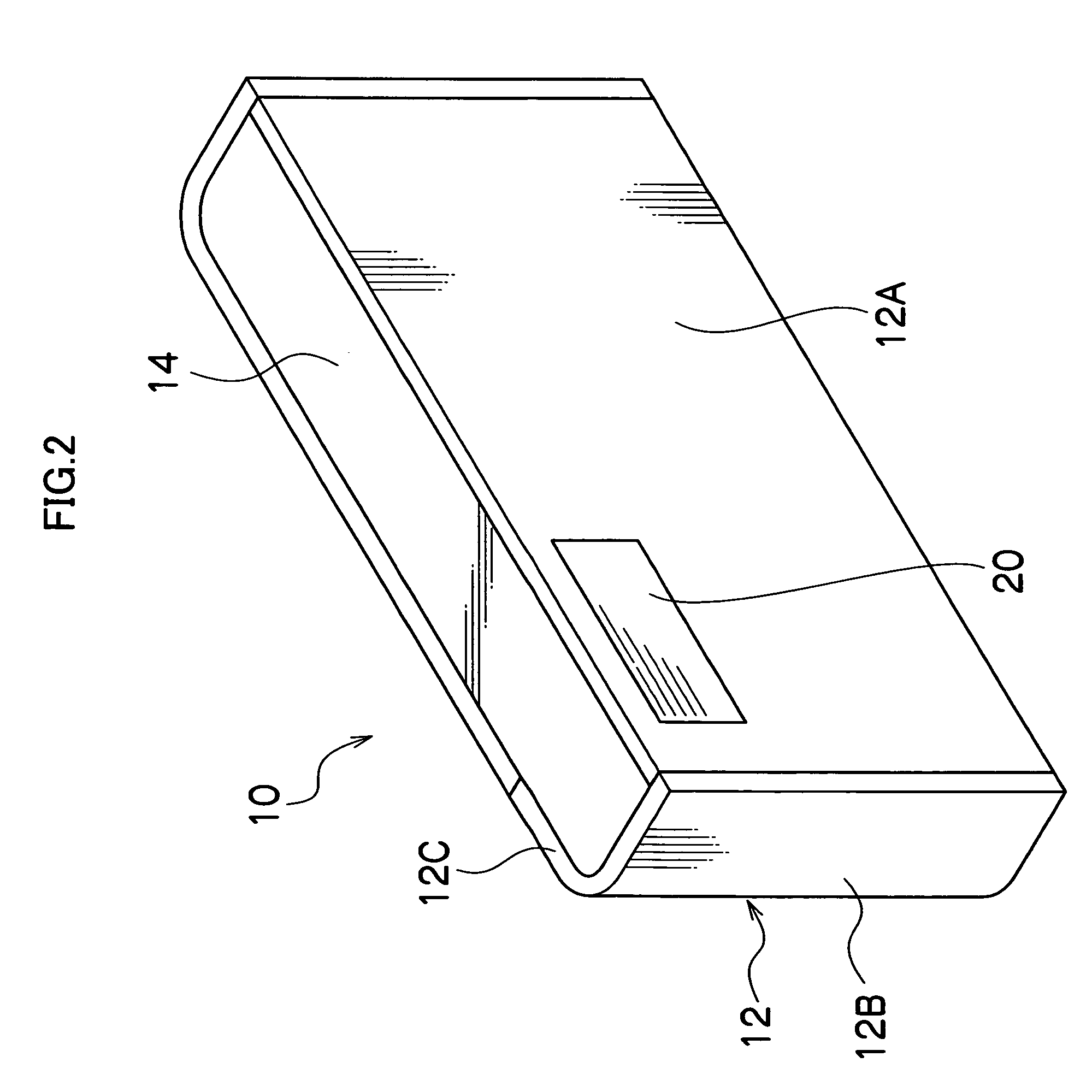
[0042]FIG. 1 is a rear perspective view of a camera main body 14 (corresponding to a first assembly) in a stored state in which a cover member 12 (corresponding to a second assembly) is closed (first position) on the camera main body 14 in a digital camera 10 while FIG. 2 is a front perspective view of the camera main body 14 in the state shown in FIG. 1. In addition, FIG. 3 is a rear perspective view of the camera main body 14 in a developed state in which the cover member 12 is opened (second position), while FIG. 4 is an explanatory diagram depicting a state in which a user is operating the digital camera 10 with his / her right hand 16 which is indicated by a double-dotted dashed line, in the state shown in FIG. 3. FIG. 4 further indicates that the cover member 12 is gripped by the right hand 16 and therefore doubles as a grip section. FIG. 5 is a front perspective view of the camera main body 14 in the state shown in FIG. 3.

[0043] The main body 14 of the digital camera 10 has an...

second embodiment

[0087]FIG. 7 is a diagram showing a digital camera 100 according to a Same or similar parts to those used in the digital camera 10 shown in FIGS. 1 to 5 are assigned same reference numerals, and descriptions thereof will be omitted.

[0088] The digital camera 100 shown in FIG. 7 is an example of a digital camera which is not equipped with the image playback start button 38, the pause button 40, the stop button 42, the fast forward button 44, and the rewind button 46 provided on the cover member 12 of FIG. 3. According to the digital camera 100, a digital camera with a completely flat body configuration with no buttons on its exterior surface may be provided by closing a cover member 12 to hide a group of operation buttons 22, 24, 26, 32 and 34. Therefore, according to the digital camera 100, portability is improved, and from a design viewpoint, the sleeker configuration results in an improved appearance.

third embodiment

[0089]FIG. 8 is a diagram showing a digital camera 110 according to a Same or similar parts to those used in the digital camera 10 shown in FIGS. 1 to 5 are assigned same reference numerals, and descriptions thereof will be omitted.

[0090] For the digital camera 110 of FIG. 8, a photography button 28 is arranged at a depressed face section 112 to be hidden by a top panel 12D of a cover member 12 which is an upper face of a camera main body 14. The photography button 28 may be hidden by the cover member 12 even when the photography button 28 is arranged in such a position.


PUM


Abstract

A camera, comprising: a first assembly; a photographic lens equipped on the first assembly; a display section equipped on the first assembly; operation members equipped on the first assembly, and a second assembly movably provided on the first assembly, and being configured to be movable between a first position at which the operation members are covered and a second position at which the operation members are exposed.

Description

BACKGROUND OF THE INVENTION [0001] 1. Field of the Invention [0002] The present invention relates to a camera, and more particularly, to a digital camera equipped with a large-screen display section and suitable for photography and playback of images. [0003] 2. Description of the Related Art [0004] In digital cameras provided with display sections such as liquid crystal monitors, the increase in size of display sections has created conflicting issues of improvement in gripability of such digital cameras and downsizing of the camera main bodies. In other words, in a digital camera equipped with a large-screen display section, only a grip portion of the camera main body must be enlarged in order to enhance gripability. Additionally, in light of the increased size in display screens, various innovations have been made on digital cameras in order to protect their display screens from scratches or stains. For instance, a digital camera with a built-in cover member for protecting a displa...

Claims


Application Information

Patent Timeline
IPC IPC(8): G03B17/00
CPCG03B17/04H04N5/2252H04N5/23212H04N23/50H04N23/51H04N23/673H04N23/65H04N23/00
Inventor MISAWA, ATSUSHI
Owner FUJIFILM CORP
Why Eureka
Try Eureka