
Antenna array including virtual antenna elements

a virtual antenna and array technology, applied in the field of multi-element antenna receivers, can solve the problems of complex operation, inconformity with requirements, and difficulty in achieving high speed and high quality of service, and achieve the effect of obviating the effects of multi-path fading, increasing the quality or reducing the effective error rate,

Inactive Publication Date: 2007-05-17
AVAGO TECH INT SALES PTE LTD
View PDF5 Cites 6 Cited by
  • Summary
  • Abstract
  • Description
  • Claims
  • Application Information

AI Technical Summary

Benefits of technology

The invention is a method and system for processing signals received by an antenna array. The system includes multiple physical antenna elements that capture multiple replicas of the signal. These replicas are then processed by signal processing chains to generate responses at different locations along the antenna array. The system can also include an interpolation module to generate additional responses based on the replicas. The technical effect of this invention is improved signal processing and more accurate spatial representation of the received signal.

Problems solved by technology

Achieving high speed and high quality of service, however, is complicated because it is desireable for mobile subscriber units to be small and lightweight, and to be capable of reliably operating in a variety of environments (e.g., cellular / microcellular / picocellular, urban / suburban / rural and indoor / outdoor).
In many wireless systems, three principal factors tend to account for the bulk of performance and capacity degradation: multipath fading, delay spread between received multipath signal components, and co-channel interference (CCI).
Increasing the quality or reducing the effective error rate in order to obviate the effects of multipath fading has proven to be extremely difficult.
Although it would be theoretically possible to reduce the effects of multipath fading through use of higher transmit power or additional bandwidth, these approaches are often inconsistent with the requirements of next-generation systems.
As mentioned above, the “delay spread” or difference in propagation delays among the multiple components of received multipath signals has also tended to constitute a principal impediment to improved capacity and performance in wireless communication systems.
It has been reported that when the delay spread exceeds approximately ten percent (10%) of the symbol duration, the resulting significant intersymbol interference (ISI) generally limits the maximum data rate.
This type of difficulty has tended to arise most frequently in narrowband systems such as the Global System for Mobile Communication (GSM).
The existence of co-channel interference (CCI) also adversely affects the performance and capacity of cellular systems.
In TDMA systems, the CCI is predominantly from one or two other users, while in CDMA systems there may exist many strong interferers both within the cell and from adjacent cells.
Although increasing the number of receive antennas enhances various aspects of the performance of multi-antenna systems, the necessity of providing a separate RF chain for each transmit and receive antenna increases costs.
It is thus apparent that as the number of receive antennas increases, overall system cost and power consumption may dramatically increase.

Method used


Image

  • Antenna array including virtual antenna elements
  • Antenna array including virtual antenna elements
  • Antenna array including virtual antenna elements

Examples


Embodiment Construction

[0031] In the following description, various aspects of the present invention will be described. However, it will be apparent to those skilled in the art that the present invention may be practiced with only some or all aspects of the present invention. For purposes of explanation, specific numbers, materials and configurations are set forth in order to provide a thorough understanding of the present invention. However, it will also be apparent to one skilled in the art that the present invention may be practiced without the specific details. In other instances, well known features are omitted or simplified in order not to obscure the present invention.

[0032] Various operations will be described as multiple discrete steps performed in turn in a manner that is most helpful in understanding the present invention, however, the order of description should not be construed as to imply that these operations are necessarily order dependent, in particular, the order the steps are presented...


PUM


Abstract

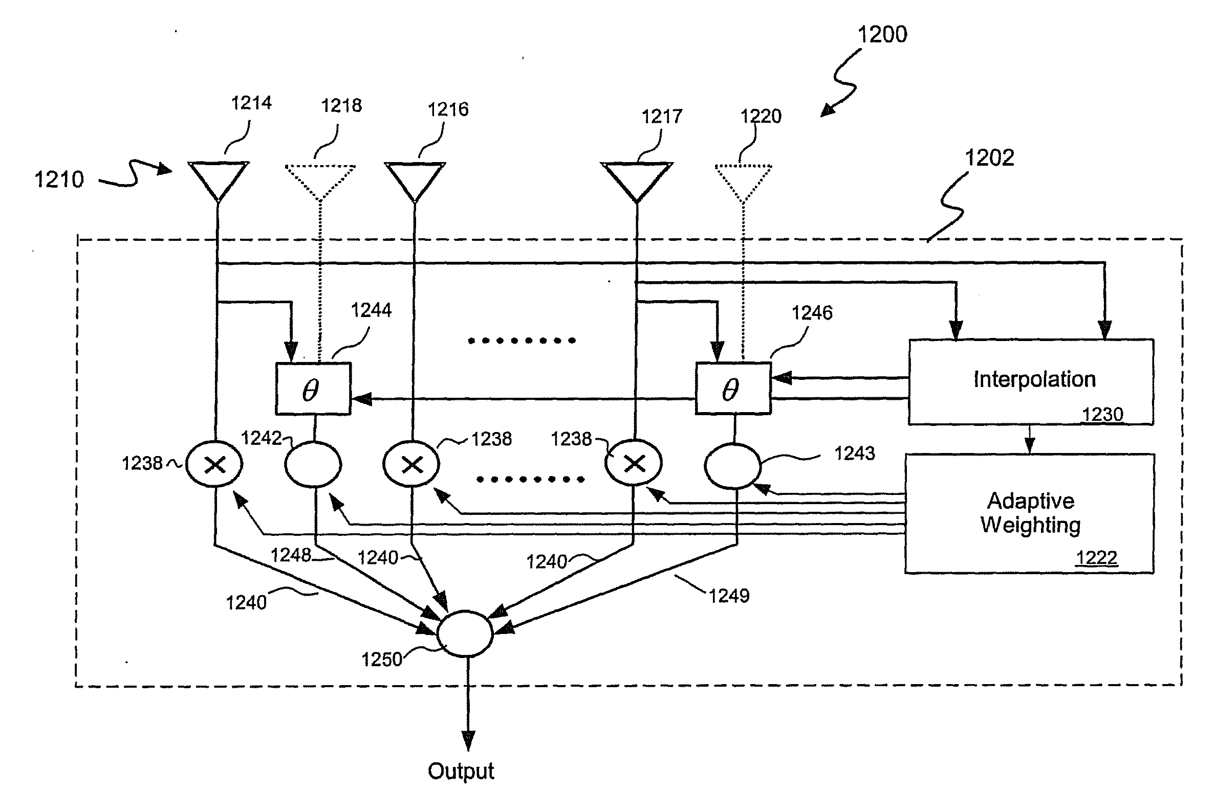
A method and associated system for effectively increasing the number of antenna elements within a multi-element antenna system through computation of a response of “virtual” antenna elements located along an antenna array. The physical elements of the array are positioned sufficiently near each other to enable synthesis of a polynomial or other mathematical expression characterizing the response of the array to receipt of an incident waveform. Values of the responses associated with the virtual antenna elements of the array may then be determined through evaluation of the synthesized polynomial or other expression. The resultant array response values associated with the virtual and physical elements of the array are then provided to an associated receiver for processing.

Description

CROSS-REFERENCE TO RELATED APPLICATION [0001] This application is a continuation of and claims priority to U.S. patent application Ser. No. 10 / 645,349, filed Aug. 21, 2003, which claims priority under 35 U.S.C. §119(e) to U.S. Provisional Application No. 60 / 405,285 entitled ANTENNA ARRAY INCLUDING VIRTUAL ANTENNA ELEMENTS, filed Aug. 21, 2002, which is incorporated herein by reference in its entirety.BACKGROUND OF THE INVENTION [0002] 1. Field of the Invention [0003] The present invention relates to a multi-element antenna receiver for radio communication systems, and more particularly to signal processing for multiple receive antennas of an associated receiver. [0004] 2. Background Information [0005] It has recently been proposed that both the performance and capacity of existing wireless systems could be improved through the use of so-called “smart” antenna techniques. In particular, it has been suggested that such techniques, coupled with space-time signal processing, could be ut...

Claims


Application Information

Patent Timeline
Patent Type & Authority Applications(United States)
IPC IPC(8): H01Q3/00H01Q1/24H01Q3/26H01Q21/22H04B7/08
CPCH01Q1/246H01Q3/2605H01Q3/2611H01Q21/22H04B7/0842H04B7/0848
Inventor VAN ROOYEN, PIETERROUX, PIETER
Owner AVAGO TECH INT SALES PTE LTD
Learn More