Noise adaptive 3D composite noise reduction

a composite noise and noise reduction technology, applied in the field of digital video filtering, can solve the problems of large volume, low noise estimation, high computational and memory bandwidth, and inability to meet the needs of many low-end applications, and achieve accurate noise estimation, high texture, and accurate noise estimation

Active Publication Date: 2007-05-17
AVAGO TECH INT SALES PTE LTD
View PDF42 Cites 15 Cited by
  • Summary
  • Abstract
  • Description
  • Claims
  • Application Information

AI Technical Summary

Benefits of technology

[0006] The objects, features and advantages of the present invention include providing a noise adaptive 3-dimensional (3D) composite noise reduction technique that may (i) provide an accurate noise estimation where an entire video frame is high texture if some area is relatively low motion, (ii) provide an accurate noise estimation where an entire video frame is high motion if some area is relatively low textured, (iii) properly estimate noise by rejecting saturated blocks, (iv) provide improved noise reduction on radio-frequency sources received over-the-air subjected to television tuner saturation, (v) provide a low cost and low complexity approach for detecting cross-luma artifacts and cross-chroma artifacts, (vi) provide a cross spatio-temporal sum-of-absolute-differences approach for effectively and efficiently detecting areas with cross-luma artifacts, (vii) correctly process a “circular sweep zone plate” pattern, (viii) filter according to the presence of a strong dot crawl and a weak dot-crawl and / or (ix) provide temporal smoothing of a noise level estimate for improved noise filtering performance.

Problems solved by technology

The existing techniques have known failures and limitations resulting in a lack of quality, complexity and expenses.
However, motion compensation is expensive both computationally and in terms of memory bandwidth.
Therefore, motion compensation noise level measurements are not suitable for many low-end, large volume applications.
In another example, spatial (i.e., block frequency distribution) based methods using comparison of measures (i.e., distributions and distributions of co-located measure differences) over a small number of adjacent frames are typically unable to distinguish between high-texture and high noise, particularly in the presence of motion.
Furthermore, motion vector analysis is complex.
Existing shimmer detection methods are also more complex than is desired for composite noise detection.
Existing methods are not bandwidth and computationally efficient for detecting cross-chroma and cross-luma.
In particular, no existing method is known to filter a “circular sweep zone plate” correctly due to unique spatio-temporal characteristics.
In addition, the existing methods do not explicitly filter differently for cases of strong dot crawl and weak dot crawl.

Method used


Image

  • Noise adaptive 3D composite noise reduction
  • Noise adaptive 3D composite noise reduction
  • Noise adaptive 3D composite noise reduction

Examples


Embodiment Construction

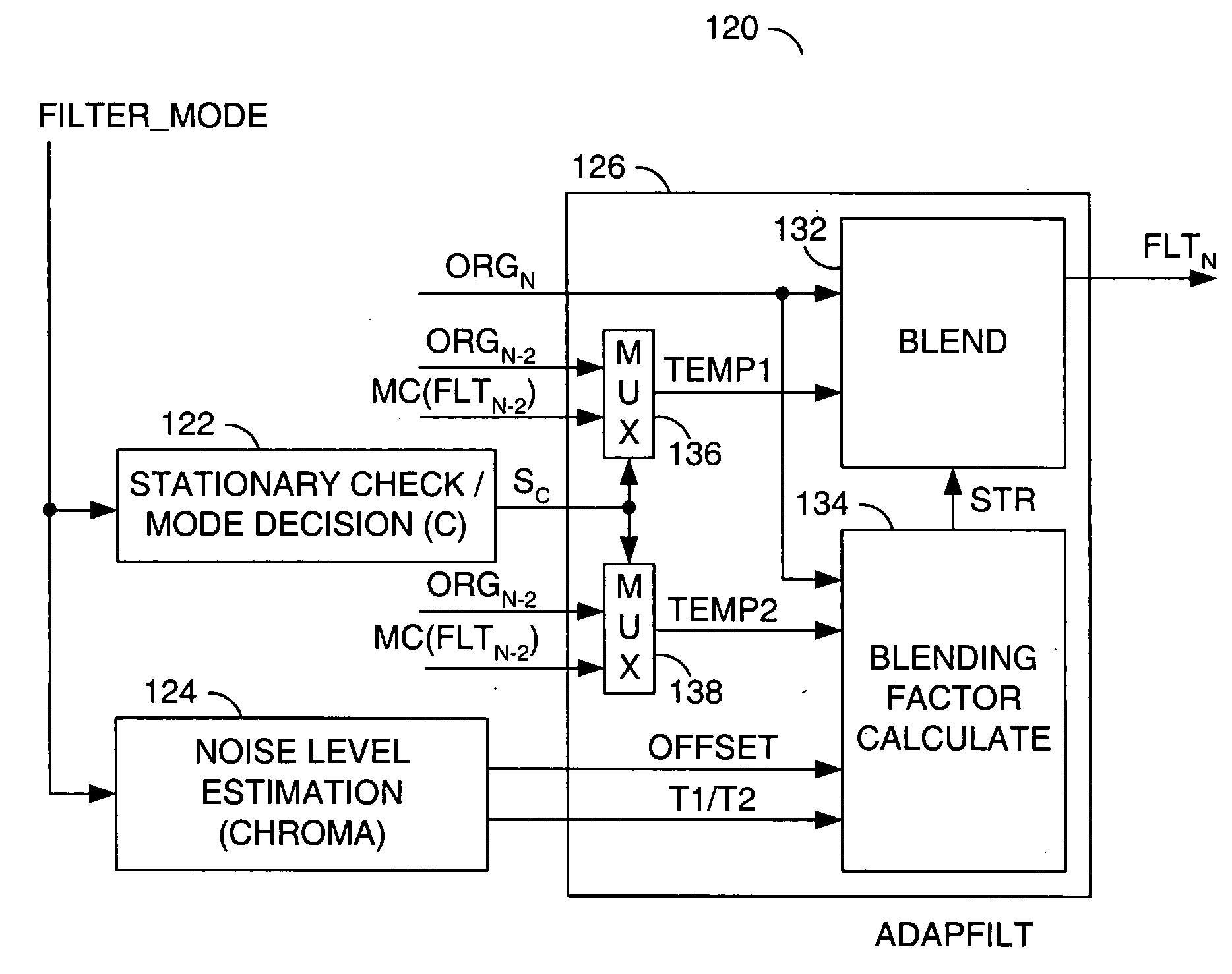
[0013] The present invention concerns a technique for reduction of both cross-luminance (cross-luma) and cross-chrominance (cross-chroma) types of composite artifacts. The technique may be applicable for both National Television System Committee (NTSC) systems and Phase Alternate Line (PAL) systems. The technique generally comprises motion compensated noise filtering to reduce both random noise and composite noise.

[0014] In the following description, the NSTC system is assumed, unless explicitly stated otherwise. Consider a sequence of digital video fields (e.g., ORG0, ORG1, ORG2, . . . ) with each field containing composite noise. For cross-chroma reduction, the following observations generally apply:

[0015] (1) Cross-chroma artifacts that appear in stationary objects in the sequence may oscillate from an original field ORGN to a previous same-parity field ORGN−2 (or ORGN−4 for PAL) between two values. A mean of the two values may be an artifact-free chrominance value.

[0016] (2) ...


PUM


Abstract

A method for filtering digital video is disclosed. The method generally includes the steps of (A) checking a plurality of original blocks in an original field for a plurality of artifacts, wherein detection of the artifacts is based on an adjustable threshold, (B) first filtering each of the original blocks having at least one of the artifacts to remove the at least one artifact and (C) second filtering each of the original blocks lacking at least one of the artifacts to remove noise, wherein the second filtering is (i) motion compensated and (ii) adaptive to a respective noise level in each of the original blocks.

Description

FIELD OF THE INVENTION [0001] The present invention relates to digital video filtering generally and, more particularly, to a noise adaptive 3-dimensional composite noise reduction technique. BACKGROUND OF THE INVENTION [0002] In composite video systems such as National Television System Committee (NTSC) systems and Phase Alternate Line (PAL) systems, color information is transmitted by a color subcarrier superimposed on a luminance signal. Therefore, the luminance signal and a chrominance signal actually share some frequency bands. As a result, two types of artifacts are commonly seen in composite video: cross-chrominance (cross-chroma) artifacts and cross-luminance (cross-luma) artifacts. The cross-chroma artifacts occur when the luminance signal contains frequency components near the color subcarrier frequency and spurious colors are generated in the picture. The cross-chroma artifacts are commonly called “bleeding” or “rainbow effects”. The cross-luma artifacts occur around edge...

Claims


Application Information

Patent Timeline
Patent Type & Authority Applications(United States)
IPC IPC(8): H04N5/00
CPCH04N5/145H04N5/21H04N9/646
Inventor WINGER, LOWELL L.NOVOTNY, PAVELJIA, YUNWEI
Owner AVAGO TECH INT SALES PTE LTD
Why Eureka
Try Eureka