Vehicular HVAC Control Systems and Methods

Inactive Publication Date: 2007-05-24
AMERICAN VEHICULAR SCI
View PDF25 Cites 60 Cited by
  • Summary
  • Abstract
  • Description
  • Claims
  • Application Information

AI Technical Summary

Benefits of technology

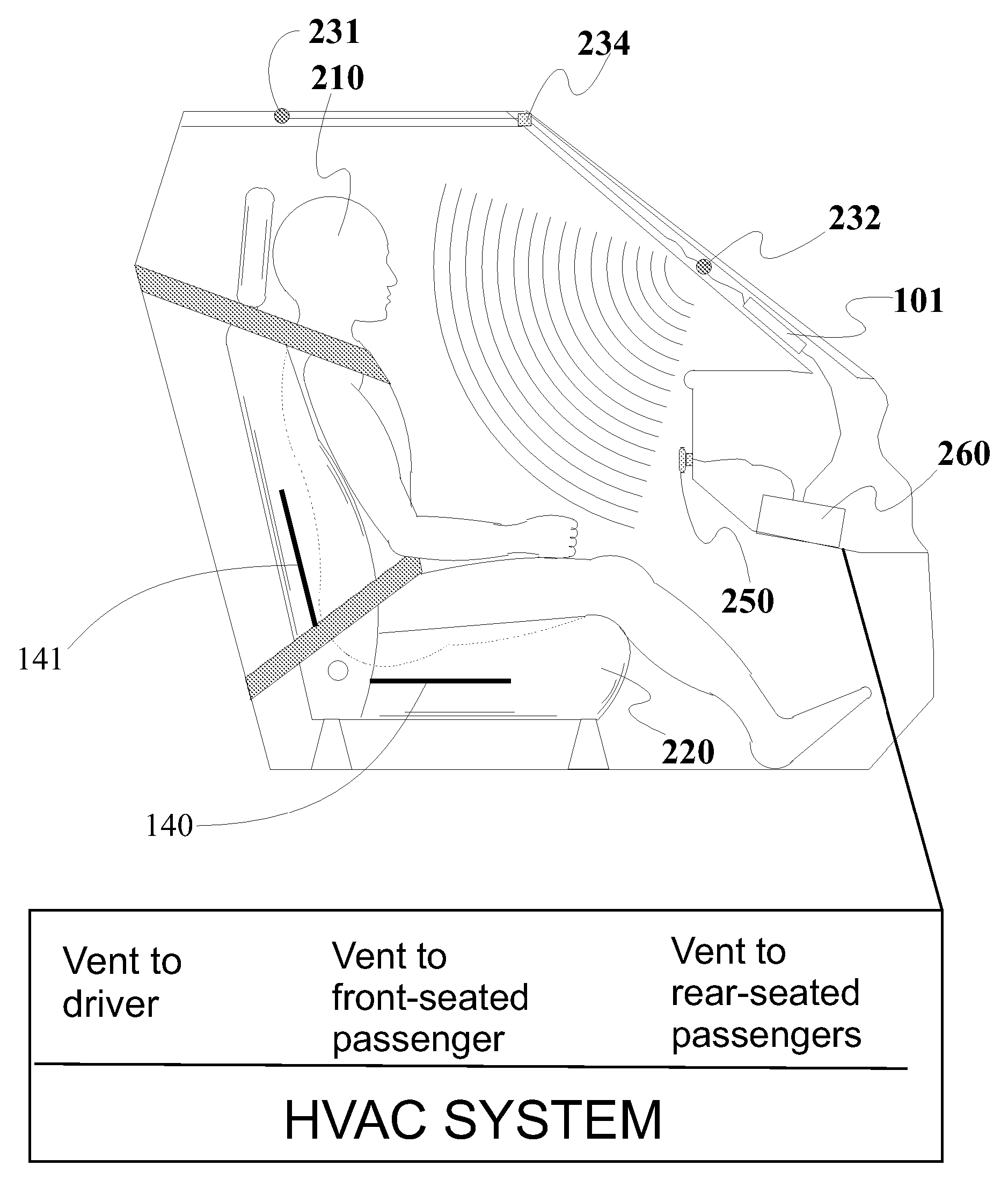
[0048] Another method for controlling a HVAC system in a vehicle in accordance with the invention includes positioning imaging devices in front of seating locations in the vehicle to obtain images of the seating locations including a face of a human occupant when present, analyzing the images to determine whether a human occupant is present in each seating location, when a human occupant is present in a seating location, locating the face of the human occupant in the image and measuring a skin temperature of t

Problems solved by technology

The drawbacks include the lack of some important sensors of vehicle interior and environment condition (such as tempe

Method used


Image

  • Vehicular HVAC Control Systems and Methods
  • Vehicular HVAC Control Systems and Methods
  • Vehicular HVAC Control Systems and Methods

Examples


Embodiment Construction

1. Basic System

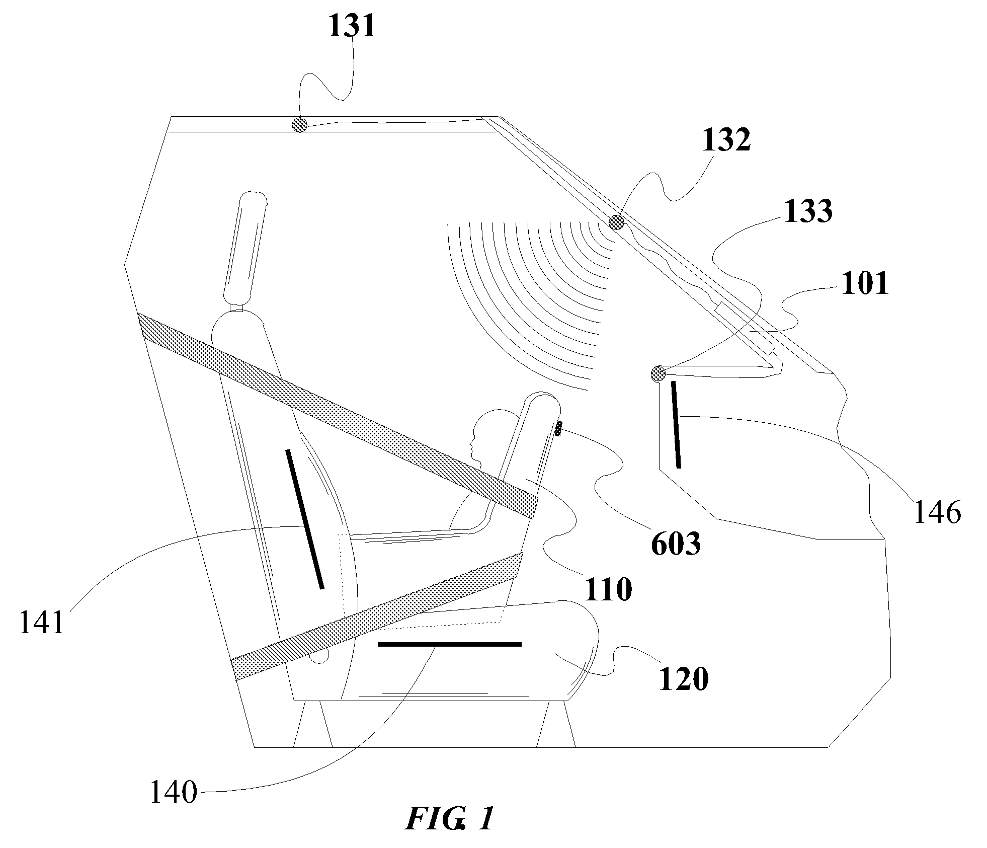
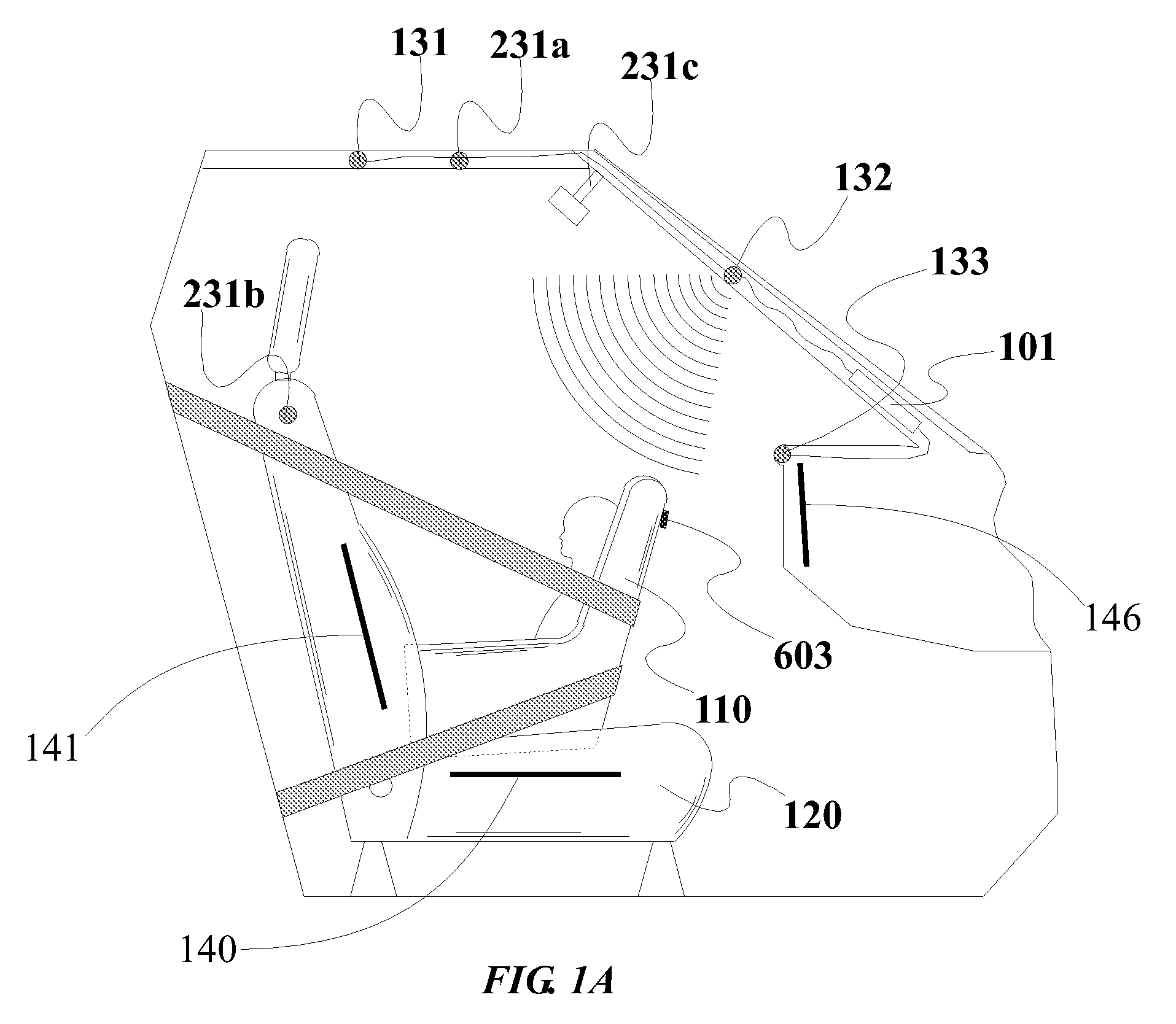
[0090] Referring to the accompanying drawings wherein the same reference numerals refer to the same or similar elements, FIG. 1 is a side view, with parts cutaway and removed of a vehicle showing the passenger compartment containing a rear facing child seat 110 on a front passenger seat 120 and a preferred mounting location for a first embodiment of a vehicle interior monitoring system in accordance with the invention. The interior monitoring system is capable of detecting the presence of an occupant and the rear facing child seat 110 (or more generally, a child seat and its orientation). In this embodiment, three transducers 131, 132 and 133 are used alone, or, alternately in combination with one or two antenna near field monitoring sensors or transducers, 140 and 141, although any number of wave-transmitting transducers or radiation-receiving receivers may be used. Such transducers or receivers may be of the type that emit or receive a continuous signal, a time va...


PUM


Abstract

Method for controlling a HVAC system in a vehicular compartment includes monitoring temperature of an occupant in the compartment from a location apart from the occupant, and controlling the HVAC system based on the monitored temperature. Occupant temperature may be monitored by infrared sensors, each arranged in an orientation to receive electromagnetic radiation from one or more seating locations in which occupants are likely to be situated. The temperature in each seating location is independently monitored. The HVAC system is controllable for each seating location based on the monitored temperature in that area. When monitoring of temperature in an area in which a driver of the vehicle is likely to be situated indicates presence of the driver, and no other areas indicate presence of a human occupant, the HVAC system is controllable such that all heat or air-conditioning provided by the HVAC system is directed to the driver.

Description

CROSS REFERENCE TO RELATED APPLICATIONS [0001] This application is a: [0002] 1. a continuation-in-part (CIP) of U.S. patent application Ser. No. 10 / 058,706 filed Jan. 28, 2002 which is: [0003] A. a CIP of U.S. patent application Ser. No. 09 / 543,678 filed Apr. 7, 2000, now U.S. Pat. No. 6,412,813, which is a CIP of U.S. patent application Ser. No. 09 / 047,704 filed Mar. 25, 1998, now U.S. Pat. No. 6,116,638, which is a CIP of U.S. patent application Ser. No. 08 / 640,068 filed Apr. 30, 1996, now U.S. Pat. No. 5,829,782, which is a continuation application of U.S. patent application Ser. No. 08 / 239,978 filed May 9, 1994, now abandoned; and [0004] B. a CIP of U.S. patent application Ser. No. 09 / 891,432 filed Jun. 26, 2001, now U.S. Pat. No. 6,513,833, which is a CIP of U.S. patent application Ser. No. 09 / 838,920 filed Apr. 20, 2001, now U.S. Pat. No. 6,778,672, which is a CIP of U.S. patent application Ser. No. 09 / 563,556 filed May 3, 2000, now U.S. Pat. No. 6,474,683, which is a CIP of U...

Claims


Application Information

Patent Timeline
IPC IPC(8): F24F7/00B60H1/00
CPCB60H1/00742B60H1/00842B60N2/002F24F11/0034F24F11/30F24F2120/10
Inventor BREED, DAVID S.JOHNSON, WENDELL C.DUVALL, WILBUR E.
Owner AMERICAN VEHICULAR SCI
Why Eureka
Try Eureka