
Methods and systems for operating a pan tilt zoom camera

Inactive Publication Date: 2007-05-24
UTC FIRE & SECURITY AMERICAS CORPORATION INC
View PDF14 Cites 18 Cited by
  • Summary
  • Abstract
  • Description
  • Claims
  • Application Information

AI Technical Summary

Problems solved by technology

For example, over time, the camera and / or PTZ assembly may require maintenance to restore a damaged or worn camera or PTZ assembly to an operable condition.
However, mechanical inaccuracies in the pan / tilt assemblies typically necessitate the presets being reprogrammed after the video camera assemblies are replaced.

Method used


Image

  • Methods and systems for operating a pan tilt zoom camera
  • Methods and systems for operating a pan tilt zoom camera
  • Methods and systems for operating a pan tilt zoom camera

Examples


Embodiment Construction

[0011] As used herein, an element or step recited in the singular and proceeded with the word “a” or “an” should be understood as not excluding plural elements or steps, unless such exclusion is explicitly recited. Furthermore, references to “one embodiment” of the present invention are not intended to be interpreted as excluding the existence of additional embodiments that also incorporate the recited features.

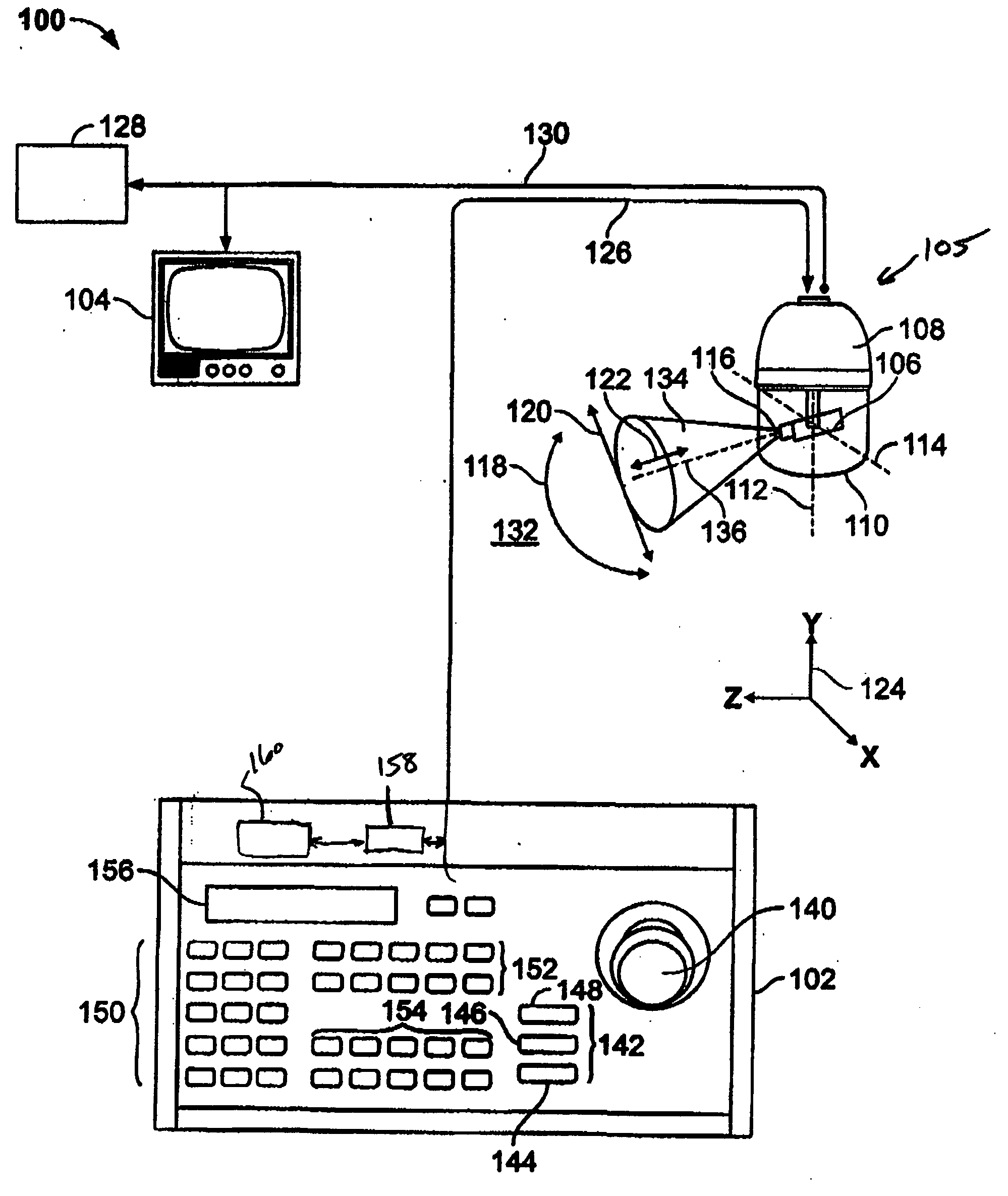
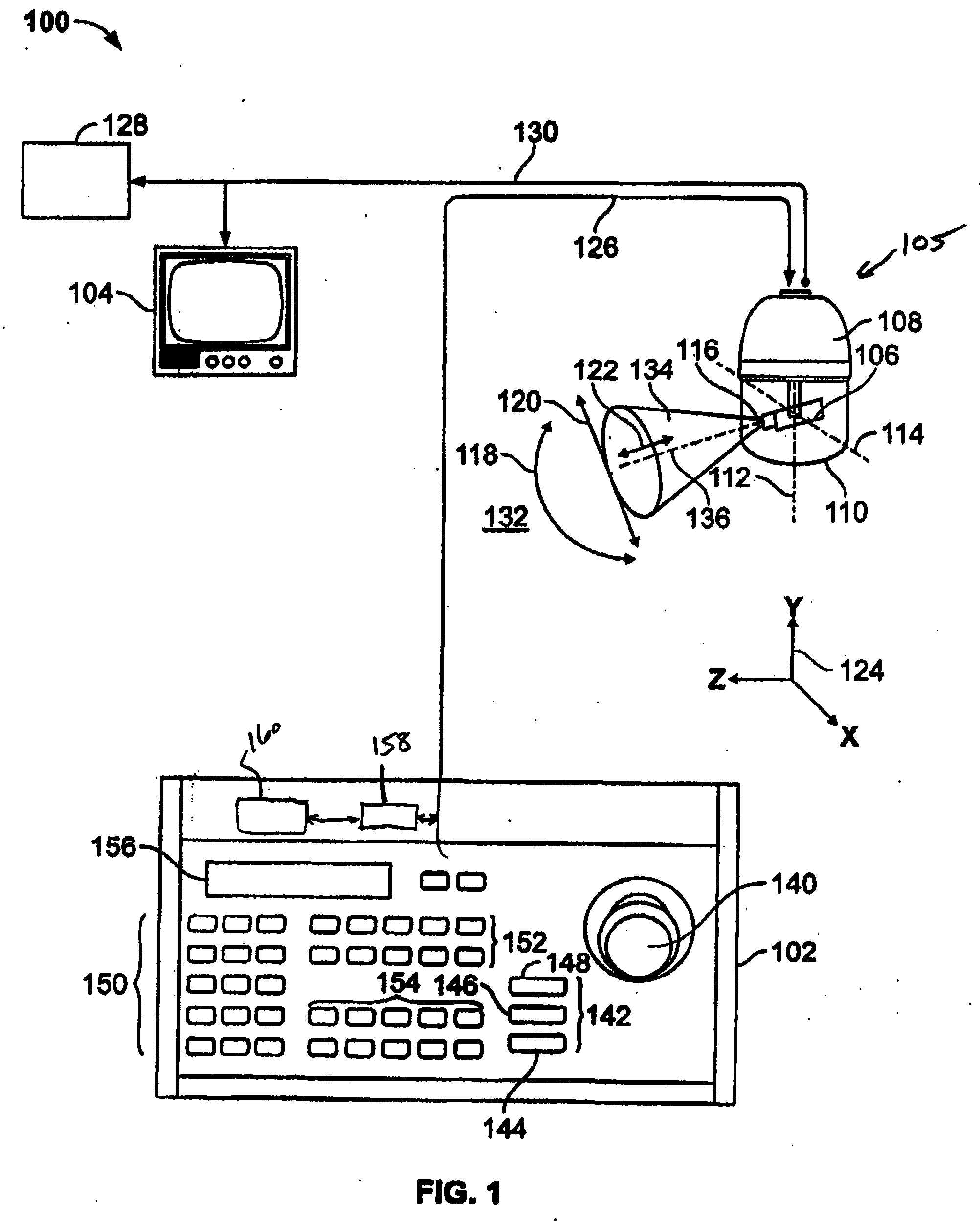
[0012]FIG. 1 is a schematic view of an exemplary video surveillance system 100 in accordance with an embodiment of the present invention. Video surveillance system 100 includes a control panel 102, a display monitor 104, and a pan, tilt, and zoom (PTZ) assembly 105. Typically, a camera 106 is housed in an enclosure 108 having a dome 110 for protecting camera 106 from the environment where camera 106 is located. In one embodiment, dome 110 is tinted to allow camera 106 to acquire images of the environment outside of enclosure 108 and simultaneously prevent individuals in the ...


PUM


Abstract

Methods and systems for a video surveillance system are provided. The system includes a video camera assembly including a base, a first pan / tilt mechanism, and a second pan / tilt mechanism. The first pan / tilt mechanism is removably coupled to the base. The second pan / tilt mechanism is configured to be coupled to the base in replacement of the first pan / tilt mechanism. The system also includes a memory configured to store pan / tilt mechanism positional calibration information, and a controller communicatively coupled to the first pan / tilt mechanism configured to receive positional calibration information for the first pan / tilt mechanism, store the positional calibration information to the memory, retrieve the positional calibration information from the memory when the first pan / tilt mechanism is removed and replaced with the second pan / tilt mechanism, and download the retrieved positional calibration information for use by the second pan / tilt mechanism.

Description

BACKGROUND OF THE INVENTION [0001] This invention relates generally to video surveillance systems and, more particularly, to assembling and disassembling camera pan, tilt, and zoom assemblies. [0002] At least some known video surveillance systems include one or more video cameras mounted in a housing along with a pan, tilt, and zoom (PTZ) assembly. The PTZ permits controlling a movement of the camera to align a viewing area of the camera with an object of interest or location of interest. The zoom portion of the mechanism may be used to adjust a field of view of the camera. The housing protects the camera from the environment in the location where the camera and PTZ assembly are mounted. [0003] At least some known video camera assemblies are equipped with “preset” controls, for example, servo mechanisms to position the camera to internally stored pan, tilt, zoom, focus, and iris positions. Using the position data, a plurality of “preset” views for each camera is stored and used to d...

Claims


Application Information

Patent Timeline
IPC IPC(8): G03B17/00
CPCG08B13/1963H04N5/232H04N23/50H04N23/695
Inventor MCCORMACK, KENNETH
Owner UTC FIRE & SECURITY AMERICAS CORPORATION INC
Learn More